End mill for orbital drilling

an orbital hole and end mill technology, applied in the direction of metal working equipment, metal-working apparatus, milling equipment, etc., can solve the problems of the performance of the conventional end mill

Active Publication Date: 2010-07-22
KENNAMETAL INC
View PDF18 Cites 19 Cited by
  • Summary
  • Abstract
  • Description
  • Claims
  • Application Information

AI Technical Summary

Benefits of technology

[0007]Briefly, according to this invention, there is provided an end mill for orbital drilling comprising a shank having a shank diameter; a neck having a neck diameter; a cutting head having a cutting diameter; a corner radius; a dish angle; and a longitudinal axis, the cutting head including a forward cutting end having a convexly curved section located between the longitudinal axis and the corner radius, wherein the convexly curved section causes material removed from a workpiece to flow radially outward from an initial contact area toward the corner radius, thereby minimizing an accumulation of material in a central portion of the forward cutting end.
[0008]In another embodiment, an end mill for orbital drilling comprises a shank having a shank diameter; a neck having a neck diameter; a cutting head having a cutting diameter; a corner radius; a dish angle; a plurality of flutes; and a longitudinal axis, the cutting head including a forward cutting end having a convexly curved section located between the longitudinal axis and the corner radius, wherein the convexly curved section causes material removed from a workpiece to flow radially outward from an initial contact area toward the corner radius, thereby minimizing an accumulation of material in a central portion of the forward cutting end.

Problems solved by technology

As a result of this accumulation of material on the cutting head, the performance of the conventional end mill suffers.

Method used


Image

  • End mill for orbital drilling
  • End mill for orbital drilling
  • End mill for orbital drilling

Examples


Embodiment Construction

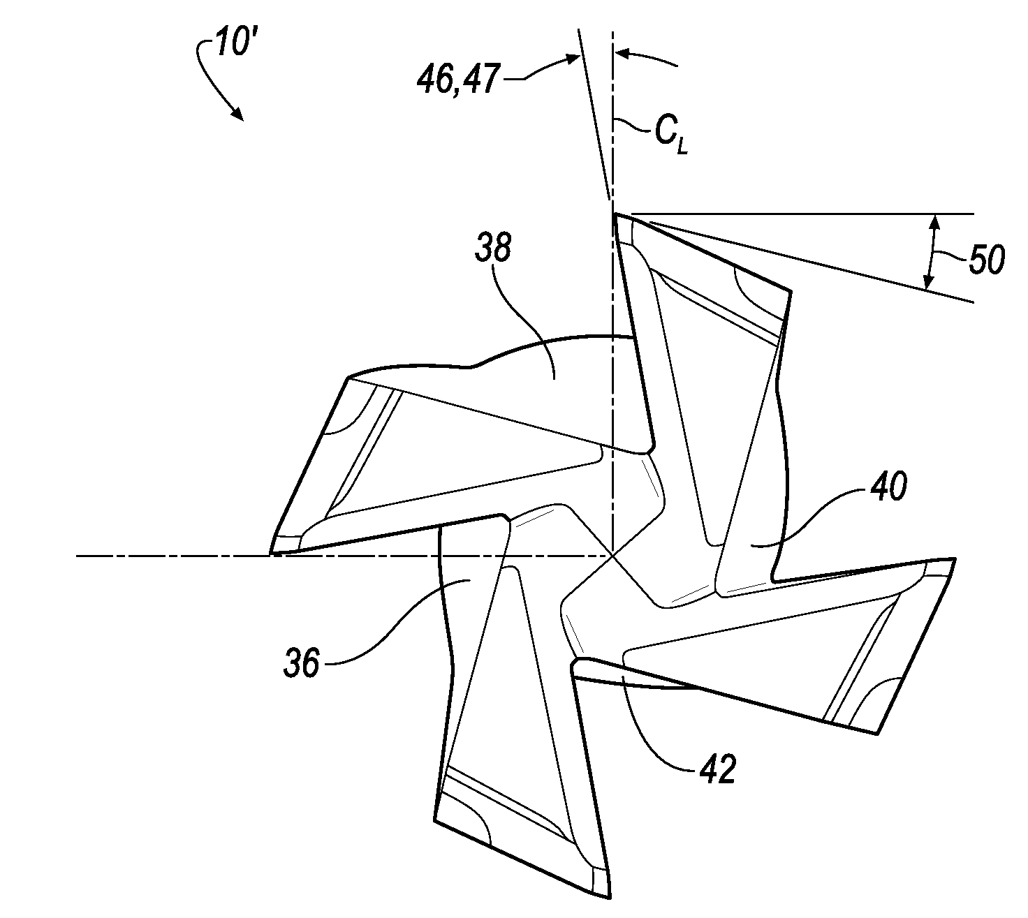
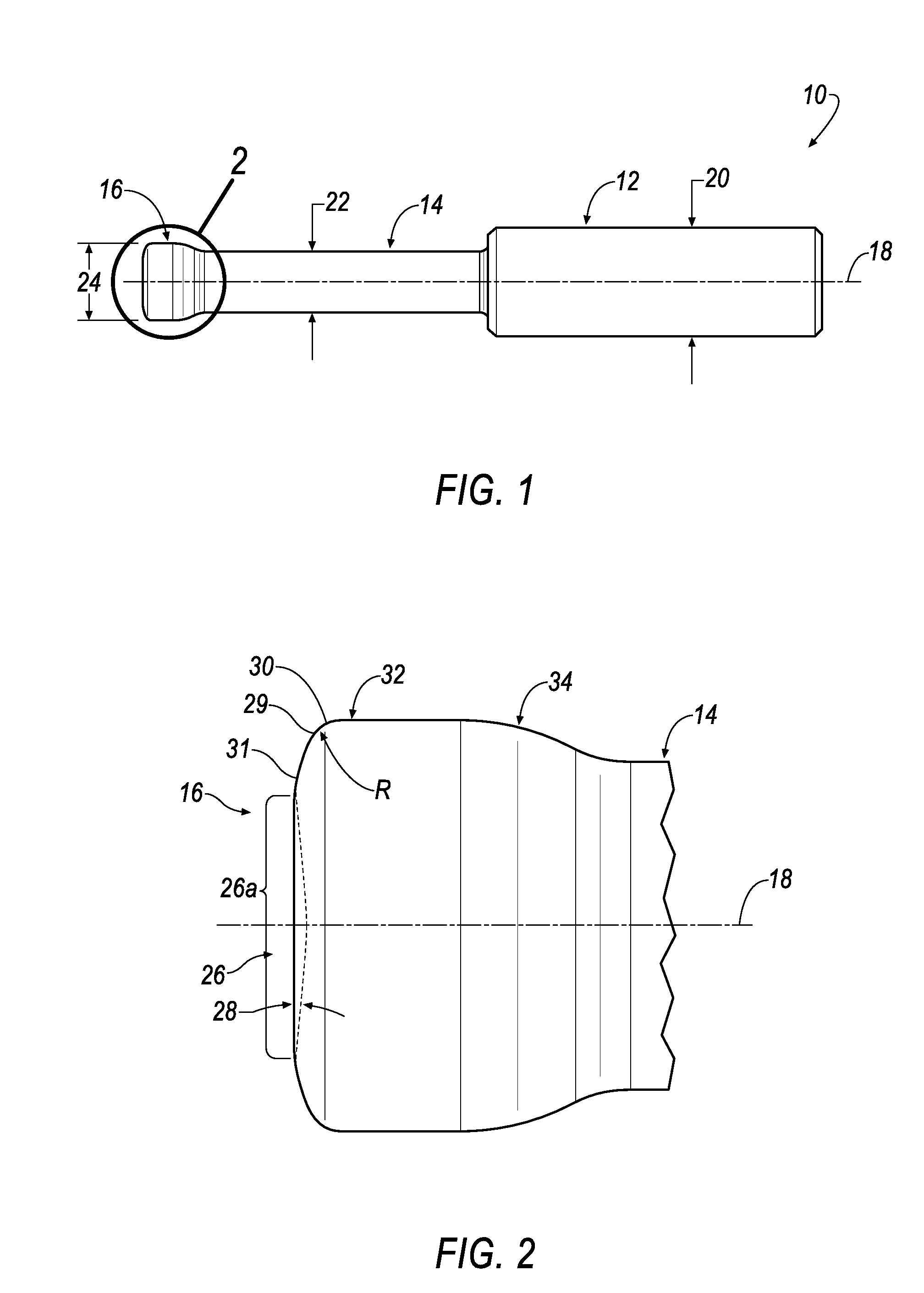
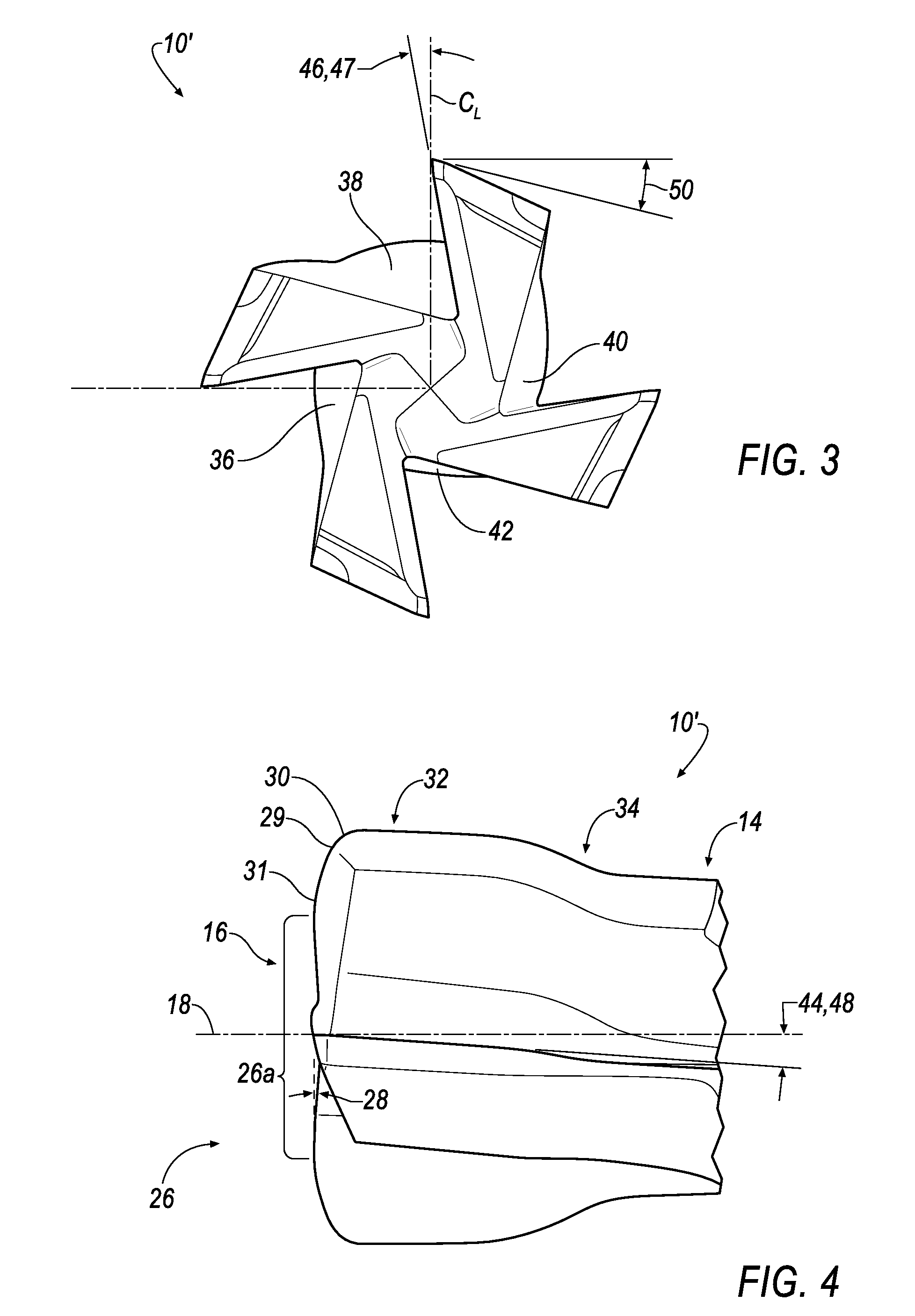
[0020]Referring to FIGS. 1 and 2, wherein like reference characters represent like elements, an end mill for orbital drilling is generally shown at 10. In general, the end mill 10 includes has a shank 12, a neck 14, a cutting head 16, and a longitudinal axis 18. In one embodiment, the shank 12 has a shank diameter 20 of approximately 0.40 inches (10.16 mm), the neck 14 has a neck diameter 22 of approximately 0.34 inches (8.64 mm), and the cutting head 16 has a cutting diameter 24 of approximately 0.40 inches (10.16 mm), which is approximately the same as the shank diameter 20. In general, the neck diameter 22 is less than the shank diameter 20 and the cutting diameter 24. For example, the neck diameter 22 can be approximately 65 to 90 percent of the shank diameter 20 and the cutting diameter 24.

[0021]The end mill 10 can be made of a substrate comprising tungsten carbide (WC) cemented with cobalt (Co) in a range between about 3 wt. % to about 15 wt. %. For improved wear resistance, t...


PUM

PropertyMeasurementUnit
helix angleaaaaaaaaaa
radial rake angleaaaaaaaaaa

Abstract

A center or non-center cutting end mill for orbital drilling includes a shank having a shank diameter; a neck having a neck diameter; a cutting head having a cutting diameter; a corner radius; a dish angle; and a longitudinal axis, the cutting head including a forward cutting end having a convexly curved section located between the longitudinal axis and the corner radius, wherein the convexly curved section causes material removed from a workpiece to flow radially outward from an initial contact area toward the corner radius, thereby minimizing the accumulation of material in a central portion of the forward cutting end.

Description

BACKGROUND OF THE INVENTION[0001]The invention relates in general to an end mill for orbital hole drilling, and in particular to an end mill having a forward cutting end with a radiused or convexly curved section that minimizes the accumulation of material from the workpiece to enable smooth drilling of the workpiece material, especially in layered materials without separating the layers.[0002]Orbital drilling is a holemaking operation by milling in which the center of an end mill orbits about the center of the intended hole while spinning on its own axis and moving in the axial direction. Orbital drilling is also known as circular milling or helical interpolation.[0003]Referring now to FIG. 7, a conventional end mill for orbital drilling is shown. The end mill 100 includes has a shank 102, a neck 104, a cutting head 106, and a longitudinal axis 108. In general, the neck diameter 112 is less than the shank diameter 110 and the cutting diameter 114. As shown in FIG. 8, the cutting he...

Claims


Application Information

Patent Timeline
Patent Type & Authority Applications(United States)
IPC IPC(8): B23C5/06
CPCB23C5/10B23C2210/084Y10T407/235Y10T407/1946Y10T407/1948B23C2220/52
Inventor VOLOKH, VLADIMIR DAVIDBOULAKHOV, SERGEI VLADIMIRSHARIVKER, LEONID BORISZEIDNER, SHAYNI, WANGYANGGALIPKO, VLADIMIR
Owner KENNAMETAL INC
Why Eureka
Try Eureka