
Orbital drilling tool unit

a drilling tool and tool body technology, applied in the direction of driving apparatus, large fixed members, milling equipment, etc., can solve the problem that stationary machine tools are not able to provide an orbital movemen

Inactive Publication Date: 2010-07-22
NOVATOR
View PDF2 Cites 23 Cited by
  • Summary
  • Abstract
  • Description
  • Claims
  • Application Information

AI Technical Summary

Benefits of technology

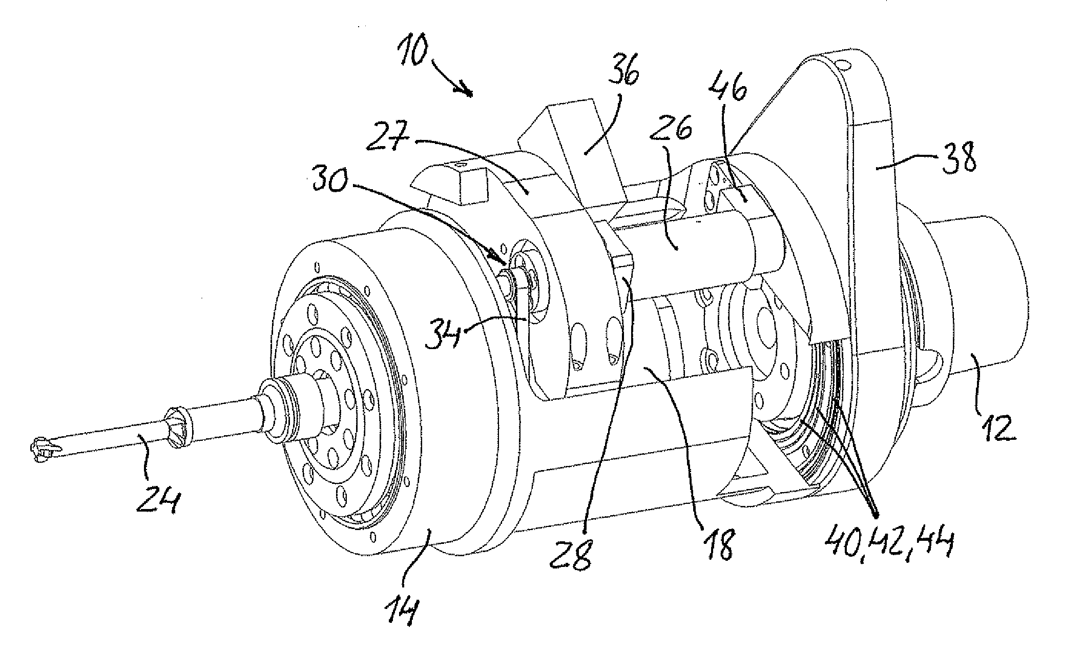
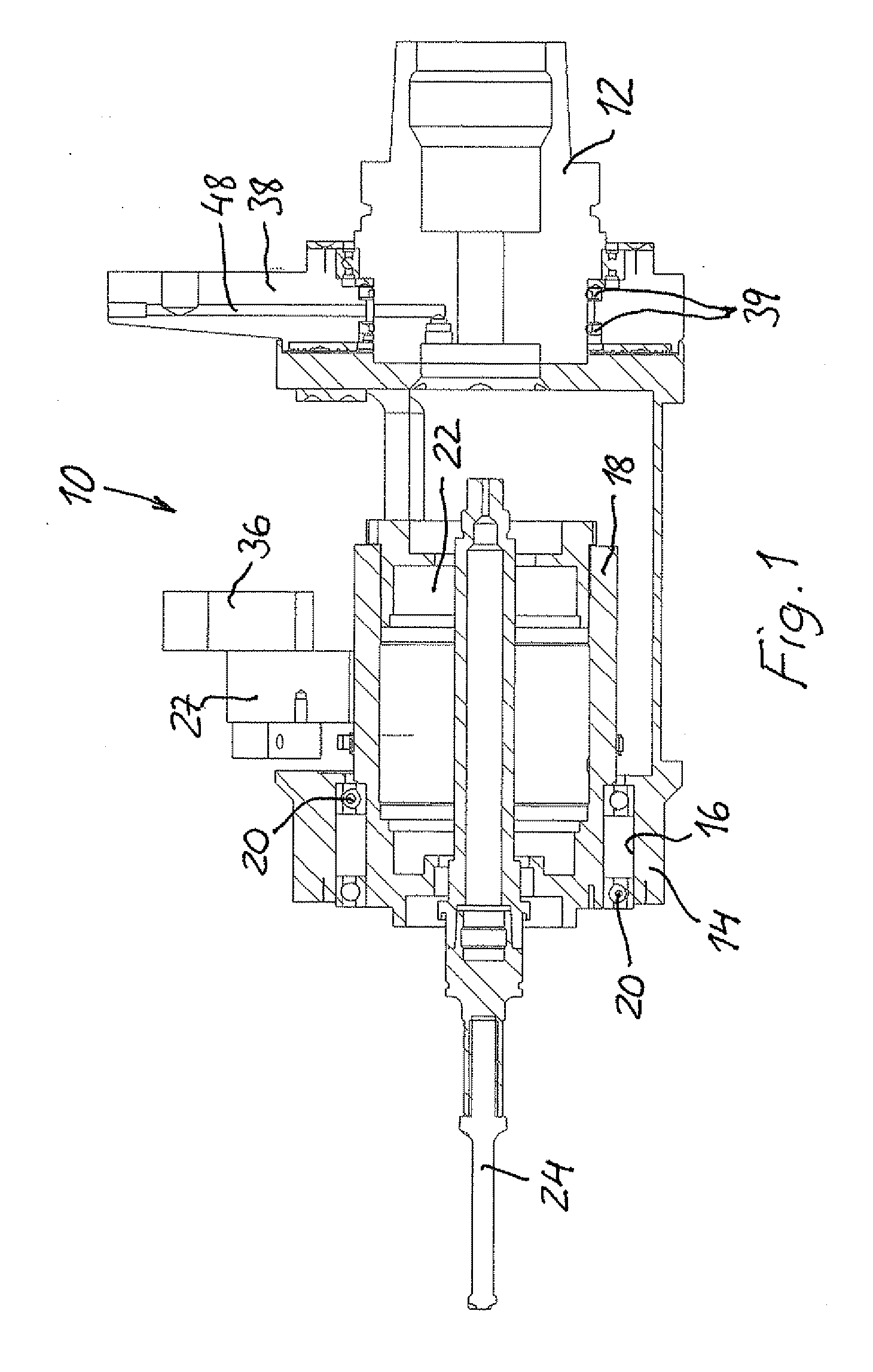
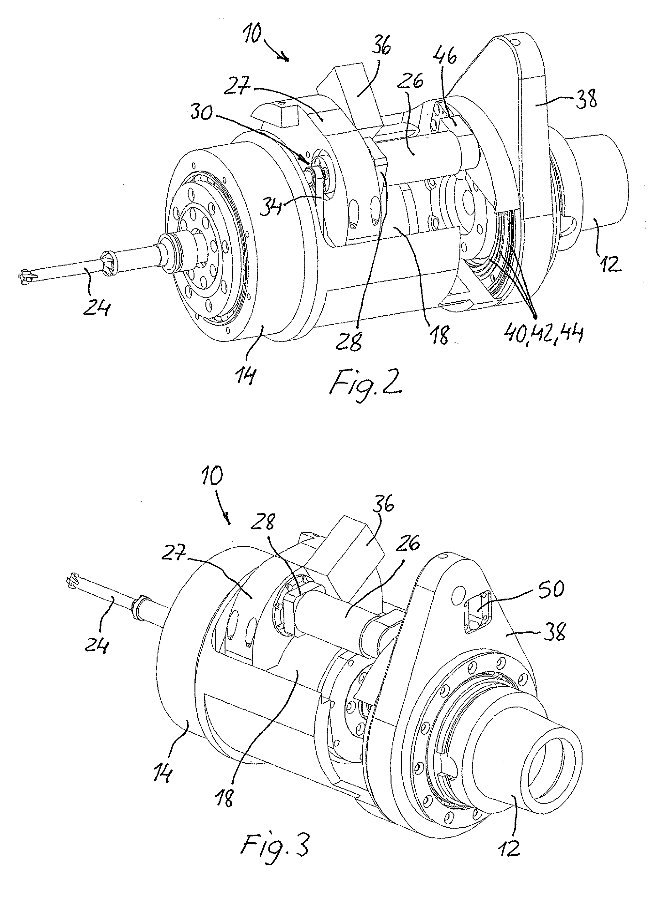
[0004]It is an object of the invention to provide an orbital drilling tool unit which is configured to be detachably mounted to a rotatable spindle of a stationary machine tool so that the latter can perform an orbital drilling operation in a workpiece without having to orbit the machine tool head or the workpiece holder. For this purpose the orbital drilling tool unit of the present invention is characterized by the features of claim 1. More particularly, the orbital drilling tool unit of the invention comprises an outer eccentric body having an eccentric, longitudinally extending cylindrical hole; an inner eccentric body rotatably supported in the eccentric hole of the outer eccentric body and having likewise an eccentric, longitudinally extending cylindrical hole; a spindle motor for detachably supporting a cutting tool and rotatably supported in the eccentric hole of the inner eccentric body; a tool holder concentrically attached to a machine tool end of the outer eccentric body for detachably mounting the latter to the machine tool spindle for rotation of the outer eccentric body together therewith; a radial offset adjusting means configured for rotating the inner eccentric body relative to the outer eccentric body for adjusting the radial offset of the spindle motor center axis (and the cutting tool axis) relative to the center axis of the machine tool spindle; and a means for transferring power to the spindle motor and the radial offset adjusting means. By using such an orbital drilling tool unit, when attached to the rotatable spindle of a stationary machine tool, orbital drilling / machining can easily be performed by the stationary machine tool without having to move the spindle head or workpiece holder thereof in x and y directions according to a system of coordinates.
[0006]Although, in a broadest aspect, the radial offset adjusting of the cutting tool could be made manually by turning a tangential screw between the housing and the inner cylinder, in a manner similar to what is disclosed in FIG. 3 of U.S. Pat. No. 6,382,890, the radial offset adjustment is preferably carried out by rotating the inner eccentric body relative to the outer eccentric body by means of a second motor which is attached to the rotatable outer eccentric body of the drilling tool unit and drivingly connected to the inner eccentric body e.g. by a belt transmission. This allows for varying the radial offset during the hole drilling process, e.g. for widening a hole or recess or for compensating a reduced diameter of the cutting tool due to wear of the cutting edges thereof.

Problems solved by technology

Although some stationary machine tools, such as CNC machine tools, are able to provide a mutual orbital movement per se between a rotating cutting tool and a workpiece either by sliding a workpiece holder in coordinated x and y directions relative to a stationary machine tool spindle, or moving the tool spindle head in correspondingly coordinated x and y directions relative to a stationary workpiece, such stationary machine tools are not able to provide an orbital movement of just the spindle motor and the cutting tool like in the portable orbital drilling machines, but the whole workpiece holder or machine spindle head of the stationary machine tool need to be moved according to a system of coordinates by means of complex drive mechanisms.

Method used


Image

  • Orbital drilling tool unit
  • Orbital drilling tool unit
  • Orbital drilling tool unit

Examples


Embodiment Construction

[0013]An orbital drilling tool unit 10 of the present invention includes 10 is configured to be exchangeably mounted to a rotatable spindle (output shaft) of a stationary machine tool, e.g. a CNC machine tool (not shown in the drawings) by means of an intermediate tool holder 12. The tool holder 12 may be of any suitable known type, such as a so called HSK, KM, Capto, or the like. FIG. 1 discloses a “HSK” tool holder 12.

[0014]The orbital drilling tool unit 10 comprises an outer eccentric body 14 which is mechanically connected to the tool holder 12 so as to be rotatable together therewith. Thus, as the machine tool spindle rotates, the outer eccentric body 14 and the tool holder 12 will rotate together with the same angular speed. The outer eccentric body 14 has an eccentric hole 16, in which an inner eccentric body 18 is rotatably mounted by means of a pair of bearings 20.

[0015]An electric (or possibly pneumatic) spindle motor 22, to which a cutting tool 24 is exchangeably attached...


PUM

PropertyMeasurementUnit
poweraaaaaaaaaa
electric poweraaaaaaaaaa
rotationaaaaaaaaaa

Abstract

An orbital drilling tool unit configured to be detachably mounted to a rotatable spindle of a stationary machine tool. The tool unit comprises an outer eccentric body having an eccentric, longitudinally extending cylindrical hole, an inner eccentric body rotatably supported in the eccentric hole of the outer eccentric body and having likewise an eccentric, longitudinally extending cylindrical hole, a spindle motor for detachably supporting a cutting tool and rotatably supported in the eccentric hole of the inner eccentric body. The machine tool end of the outer eccentric body is configured to be concentrically mounted to a tool holder attached to the machine tool spindle for rotating the outer eccentric body. A radial offset adjusting means is configured for rotating the inner eccentric body relative to the outer eccentric body for adjusting the radial offset of the spindle motor center axis relative to the center axis of the machine tool spindle, and a means is provided for transferring power to the spindle motor for rotating the cutting tool.

Description

BACKGROUND OF THE INVENTION[0001]The present invention relates to an orbital drilling tool unit configured to be detachably mounted to a rotatable spindle of a stationary machine tool according to the preamble of claim 1.[0002]Portable or hand-hold orbital drilling machines are previously known (cf. eg. U.S. Pat. No. 6,382,890 B2), which include a fixed housing for a rotatable outer eccentric cylinder having an eccentric, longitudinally extending cylindrical hole, an inner eccentric cylinder rotatably supported in the eccentric hole of the outer cylinder and having likewise an eccentric, longitudinally extending cylindrical hole, and a spindle motor for detachably supporting a cutting tool and supported in the eccentric hole of the inner cylinder. Such portable orbital drilling machines are preferably used in the aircraft and space industries and are usually temporarily fixated to a drill template for drilling holes in workpieces of fiber-reinforced composite materials to which the ...

Claims


Application Information

Patent Timeline
Patent Type & Authority Applications(United States)
IPC IPC(8): B23B43/00
CPCB23B35/00B23B41/16B23B43/00B23C3/02B23C2220/52B23Q5/046Y10T409/307112Y10T409/307616
Inventor MEJERWALL, STEFAN
Owner NOVATOR
Learn More