
Disposable safety syringe structure

a safety syringe and syringe technology, applied in the direction of intravenous devices, antipyretics, infusion needles, etc., can solve the problems of high manufacturing cost, complicated stricture, and easy piercing of users or others by injection needles, and achieve the effect of simplifying the structure and lowering the cos

Inactive Publication Date: 2010-07-22
CHEN CHO YING
View PDF2 Cites 20 Cited by
  • Summary
  • Abstract
  • Description
  • Claims
  • Application Information

AI Technical Summary

Benefits of technology

"The present invention provides a disposable safety syringe structure that simplifies the structure and lowers the cost. The structure includes a barrel body, a positioning seat, and a plunger. After injecting liquid medicine, the plunger is pushed to drive the needle out of the needle seat and into the patient's skin. The needle seat is then detached from the barrel body and retracted into the barrel body, providing a convenient and quick application and preventing users and others from being pierced and injured by the injection needle."

Problems solved by technology

As conventional disposable safety syringe structures generally have the issues of a complicated stricture and a high manufacturing cost.
Furthermore, after a liquid medicine is injected, and a plunger of a push rod connected to a needle seat of an injection needle are retracted, there is a relatively large resistance with internal walls of the barrel body, and thus the connected structure of the conventional plunger and needle seat may be detached by mistake.
Furthermore, it is necessary to apply a large force such as pressing the injection needle against a desktop in order to push the push rod for the application, and users or others may be pierced or injured by the injection needle easily if the pushing of the push rod slips.

Method used


Image

  • Disposable safety syringe structure
  • Disposable safety syringe structure
  • Disposable safety syringe structure

Examples


Embodiment Construction

[0011]The technical characteristics of the present invention will become apparent with the detailed description of the preferred embodiments and the illustration of the related drawings.

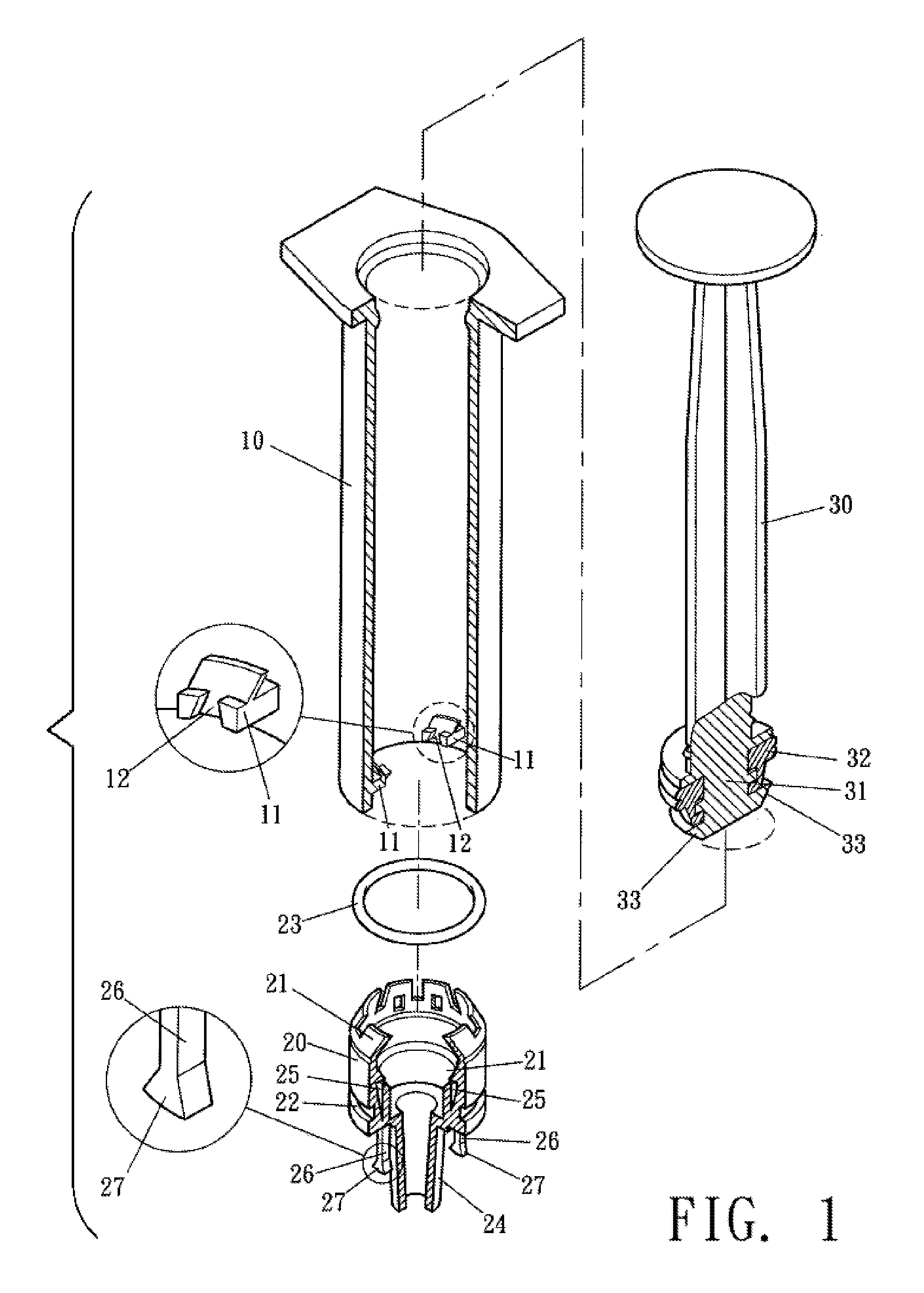
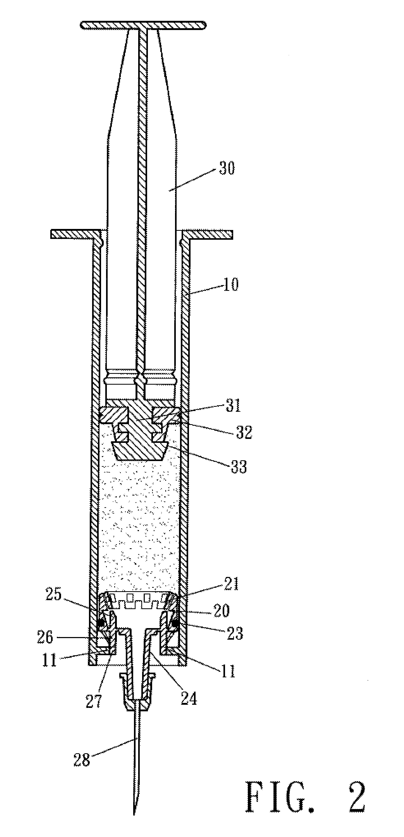
[0012]With reference to FIGS. 1 and 2, the disposable safety syringe structure comprises a barrel body 10, a needle seat 20, a push rod 30, a plunger 31, a positioning seat 11 disposed inside a distal end of the barrel body 10, a latch slot 12 formed and disposed on the positioning seat 11, a sheath section 24 disposed at a front end of the needle seat 20 for combining an injection needle 28, an elastic inverted hook plate 21 with an inwardly folded at a rear end, and a circular groove 22 disposed around the needle seat 2 for combining an anti-leak ring 23. In addition, a protruding pillar 26 is disposed at a front end of the needle seat 20, and a latch block 27 is protruded separately from ends of both opposites sides of the protruding pillar 26, and the needle seat 20 contains a guide pillar 25 int...


PUM


Abstract

A disposable safety syringe structure provides a safe application of an injection syringe and comprises a barrel body having a positioning seat and a latch slot, and the needle seat includes an inverted hook plate, a protruding pillar, a latch block, a push rod, and a plunger having a circular flange, such that when a liquid medicine is injected, the latch block of the protruding pillar of the needle seat is combined with the latch slot of the positioning seat of the barrel body, and after the liquid medicine is injected, the plunger of the push rod is forced to be plugged into the needle seat integrally, and the latch block of the protruding pillar is separated from the latch slot of the positioning seat, and the needle seat together with the injection needle are hidden into the barrel body to prevent the injection needle from piercing users and others.

Description

BACKGROUND OF THE INVENTION[0001]1. Field of the Invention[0002]The present invention relates to a disposable safety syringe structure, and more particularly to an improved safety syringe structure having a needle seat of an injection needle installed in a barrel body, such that after a liquid medicine is injected, a plunger of a push rod can be plugged into the needle seat and coupled integrally with the needle seat, and the needle seat can be detached and slid to achieve the effect of hiding the needle seat and its injection needle into the syringe, so as to prevent users and others from being pierced and injured by the injection needle and provide a convenient use of a safety syringe.[0003]2. Description of the Related Art[0004]As conventional disposable safety syringe structures generally have the issues of a complicated stricture and a high manufacturing cost. Furthermore, after a liquid medicine is injected, and a plunger of a push rod connected to a needle seat of an injectio...

Claims


Application Information

Patent Timeline
Patent Type & Authority Applications(United States)
IPC IPC(8): A61M5/50
CPCA61M5/322A61M2005/323A61P29/00
Inventor CHEN, CHO-YING
Owner CHEN CHO YING
Learn More