Interbody fusion device and method of operation

a fusion device and body technology, applied in the field of interbody fusion devices, can solve the problems of poor results of the interbody device and the need for considerable access to the method

Inactive Publication Date: 2010-07-22
INCITE INNOVATION
View PDF65 Cites 192 Cited by
  • Summary
  • Abstract
  • Description
  • Claims
  • Application Information

AI Technical Summary

Benefits of technology

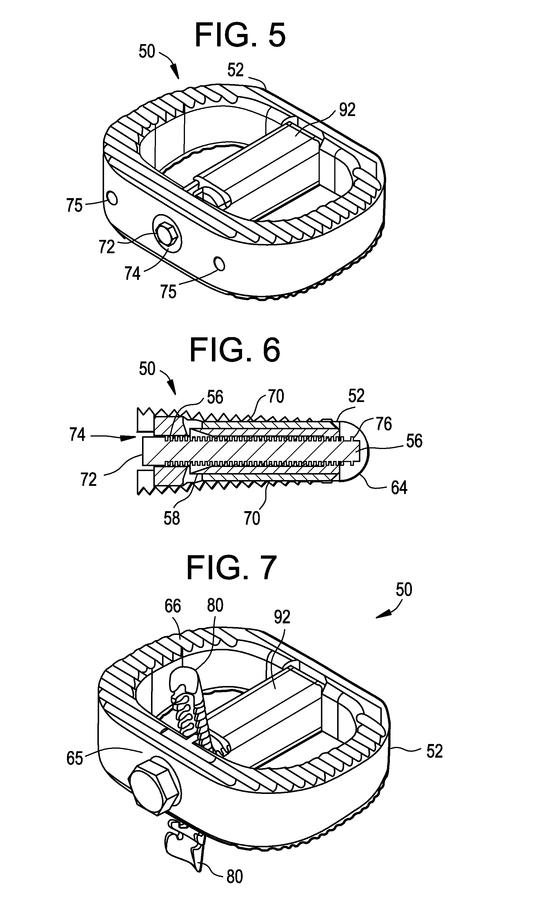
[0037]FIGS. 72-76 are an illustration of another embodiment of an anchor having a smaller profile for use with the interbody fusion device shown in FIGS. 1-29;

Problems solved by technology

Studies have shown that interbody devices have poor outcomes when they are not combined with a method of fixation.
This method requires considerable access due to the extreme angle of insertion for the screws.

Method used


Image

  • Interbody fusion device and method of operation
  • Interbody fusion device and method of operation
  • Interbody fusion device and method of operation

Examples


Embodiment Construction

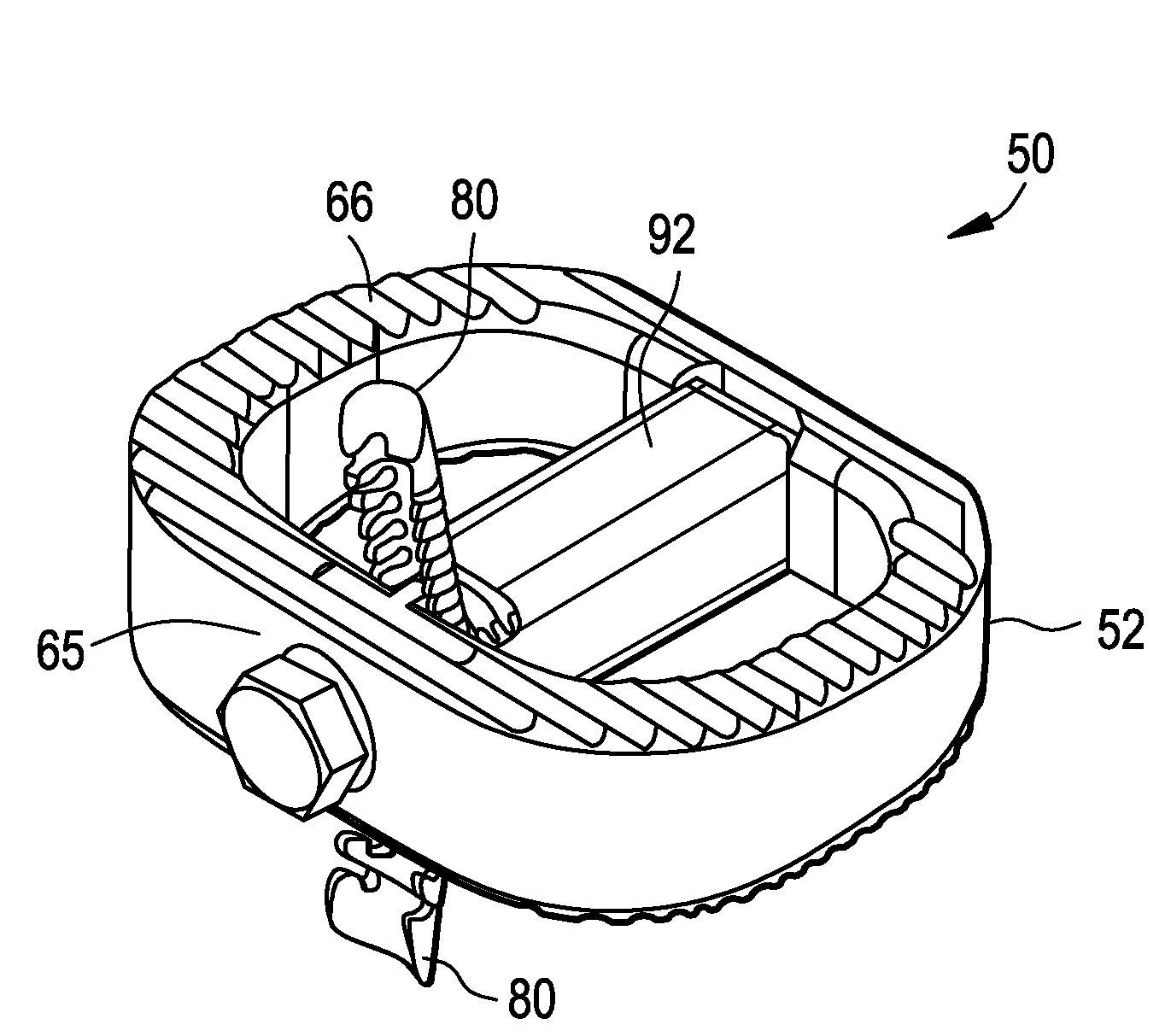
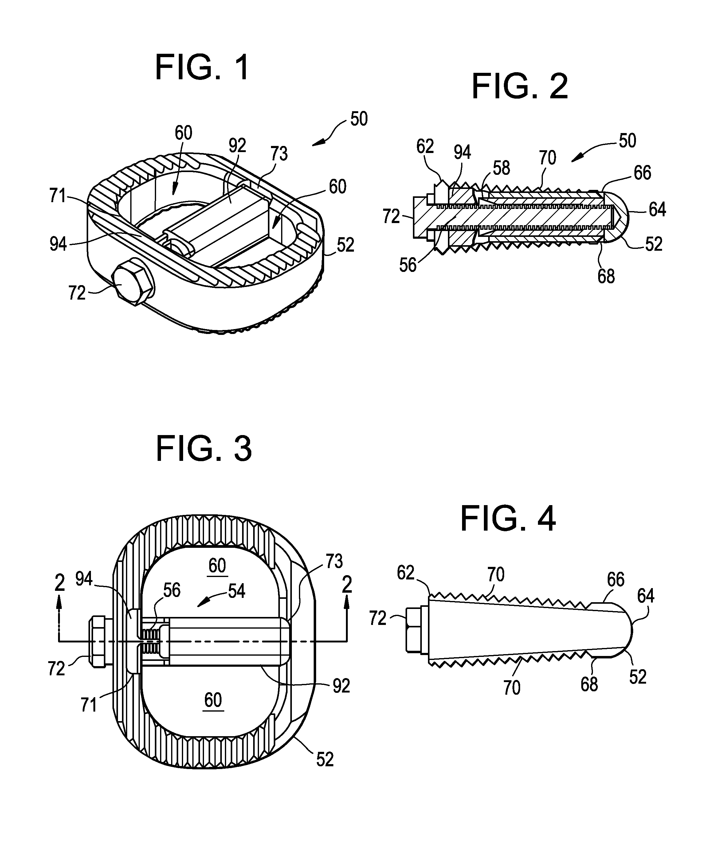
[0055]Referring to FIGS. 1-13, an exemplary interbody fusion device 50 having an interbody cage 52 and a fixation device 54 is illustrated. The interbody cage 52 can be used alone with supplemental fixation, such as rods and screws or a plate for example, or with the included fixation device 54, thereby providing a stand-alone design. The interbody cage 52, can be constructed of various biocompatible materials including, but not limited to, titanium or a polymer such as polyetheretherketone (PEEK) for example. With the fixation device 54 in place, the interbody fusion device 50 would be placed between the adjacent vertebrae after the partial or complete disc removal as illustrated in FIGS. 112-114. Once in place, the fixation device 54 would be actuated through a screw member 56. This action would deploy the anchor 58 or anchors into the adjacent superior and inferior vertebral bodies 112, 114 (FIG. 112), thereby fixing the implant in place. Thus the interbody fusion device 50 provi...


PUM


Abstract

An interbody fusion device is provided that includes an interbody cage, a fixation system and an actuation mechanism to deploy one or more blades. The cage acts as an intervertebral spacer and provides resistance to the compressive loads in the spinal column. The fixation system includes an anchor and a ramp. These components could be manufactured from various medical grade materials.

Description

CROSS REFERENCE TO RELATED APPLICATIONS[0001]The present application claims priority to U.S. Provisional Patent Application entitled “Interbody Fusion Device”, Ser. No. 61 / 145,787 filed on Jan. 20, 2009, which is incorporated by reference herein in its entirety.BACKGROUND OF THE INVENTION[0002]The subject matter disclosed herein relates to an interbody fusion device, such as that used in lumbar or cervical spine procedures for example, and in particular relates to a stand-alone interbody fusion device having a self-contained fixation system.[0003]Interbody fusion devices are common in spine procedures today. These devices encompass many products in the marketplace. Implants are constructed from PEEK, titanium and various other materials and have been designed for insertion through anterior, posterior and lateral approaches. Typically, interbody devices require additional fixation to create a fusion across the intended vertebral level. In lumbar surgery, this supplemental fixation ca...

Claims


Application Information

Patent Timeline
Patent Type & Authority Applications(United States)
IPC IPC(8): A61F2/44
CPCA61F2/4455A61F2/4465A61F2/447A61F2002/30405A61F2002/30443A61F2002/30504A61F2002/30509A61F2002/30576A61F2002/30579A61F2002/30904A61F2002/4475A61F2002/4627A61F2002/4629A61F2220/0025A61F2220/0041A61F2310/00023A61F2002/30433A61F2002/305A61F2002/30507A61F2002/30593
Inventor KIRWAN, JOHN M.BROWN, R. QUINNPFABE, HUBERT W.
Owner INCITE INNOVATION
Why Eureka
Try Eureka