Gripping apparatus for capping assemblies in container packaging machines

a technology for packaging machines and grippers, which is applied in the direction of caps, rotating screw stopper insertion, application, etc., can solve the problems of affecting the operation of the gripper arm, the operation in question is even more difficult, and the adapter installed originally with the gripper arm needs to be completely renewed, so as to facilitate and expedite the operation of replacing, renewing worn or degraded parts, and reducing the cos

Inactive Publication Date: 2010-07-29
AZIONARIA CONSTR MASCH AUTOMATICHE A C M A SPA
View PDF21 Cites 20 Cited by
  • Summary
  • Abstract
  • Description
  • Claims
  • Application Information

AI Technical Summary

Benefits of technology

[0019]One object of the invention, in particular, is to provide a gripping apparatus for capping assemblies such as will facilitate and expedite the operations of replacing the adapters of the gripping mechanism, whether for the purpose of effecting a changeover from one size or style of cap to another, or of renewing worn or degraded parts.
[0020]A further object of the invention is to achieve a significant reduction in the costs incurred routinely by replacing the adapters of conventional gripping apparatus, shortening the interval of time for which the production cycle must be suspended in order to effect the replacement.

Problems solved by technology

Whilst the gripping apparatuses currently in use are able to apply caps to containers satisfactorily, the applicant finds nonetheless that they are not entirely free of drawbacks and could be improved in a number of respects, mainly with regard to the simplicity and practicality of the operation by which the adapters presenting the rubber pads are removed from and refitted to the arms of the gripper, but with regard also to the time needed to carry out the steps of removing and fitting the adapters, and the cost disadvantages connected with these same removal and refitment operations.
Consequently, given the appreciable number of grippers normally in operation on conventional capping units, and therefore the appreciable number of single arms carrying respective adapters, these removal and refitment procedures tend to be significantly long and somewhat impractical.
The operations in question represent an even greater burden when there is a change of production size involved, in other words, a changeover requiring the replacement of all the adapters in use on the grippers of a given capping unit with others presenting rubber pads of different size and shape, suitable for handling caps that are structurally dissimilar to those utilized in production previously.
The same problem arises when, as a result of the rubber pads becoming worn and degraded, the adapters installed originally with the gripper arms need to be renewed completely by fitting replacement adapters with fresh rubber pads.
Moreover, given the complexity of the prior art capping units in question, the operating space needed to effect the removal and / or refitment of the adapters is somewhat limited, with the result that the tasks of loosening and / or tightening clamp screws employing conventional instruments, equipment and / or tools such as keys, screwdrivers and the like, tend to be obstructed and consequently prolonged.
Self-evidently, every time the adapters of the gripping apparatus need to be replaced or renewed, the operation impacts significantly on the cost of capping the containers, as a proportion of overall production costs.
However, the expedient of preparing numerous sets of gripper assemblies each dedicated to a particular cap size, simply in order to minimize down time during the production cycle, is economically expensive and has little advantage.

Method used


Image

  • Gripping apparatus for capping assemblies in container packaging machines
  • Gripping apparatus for capping assemblies in container packaging machines
  • Gripping apparatus for capping assemblies in container packaging machines

Examples


Embodiment Construction

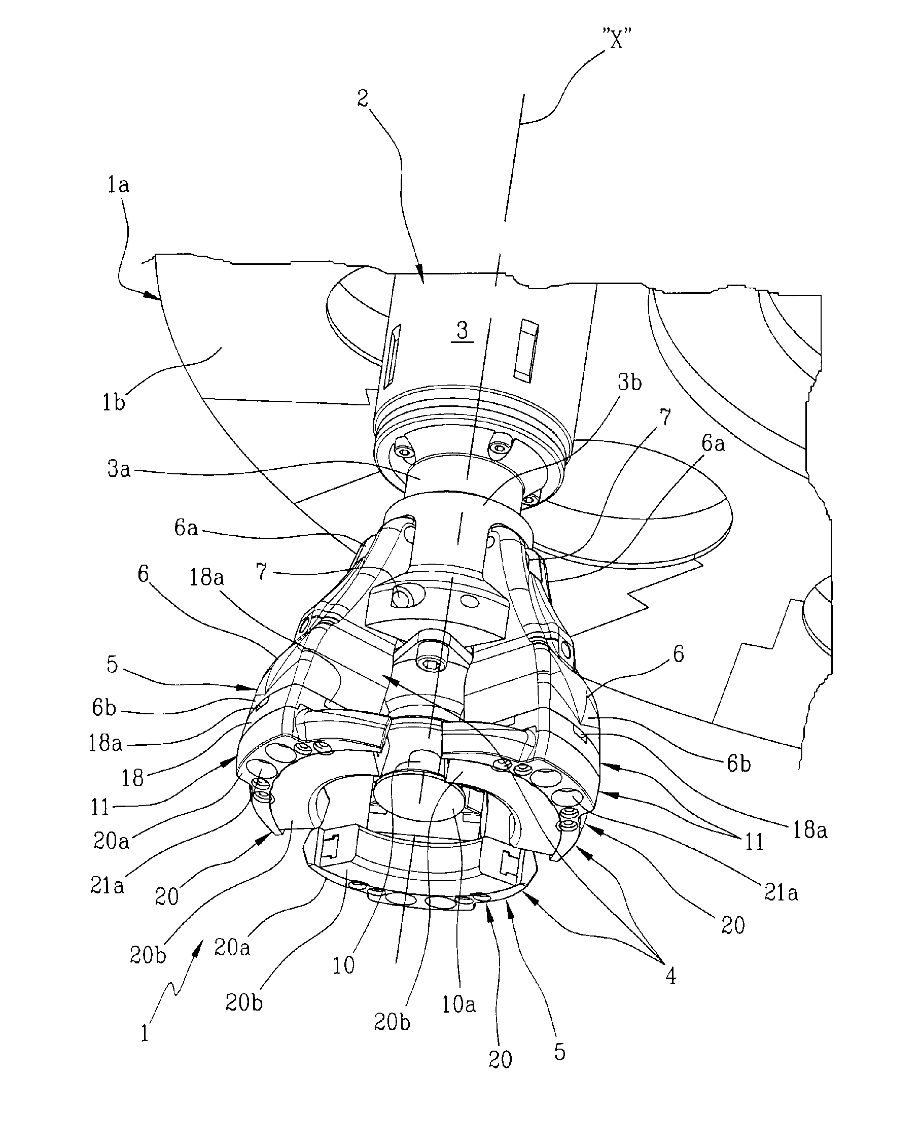
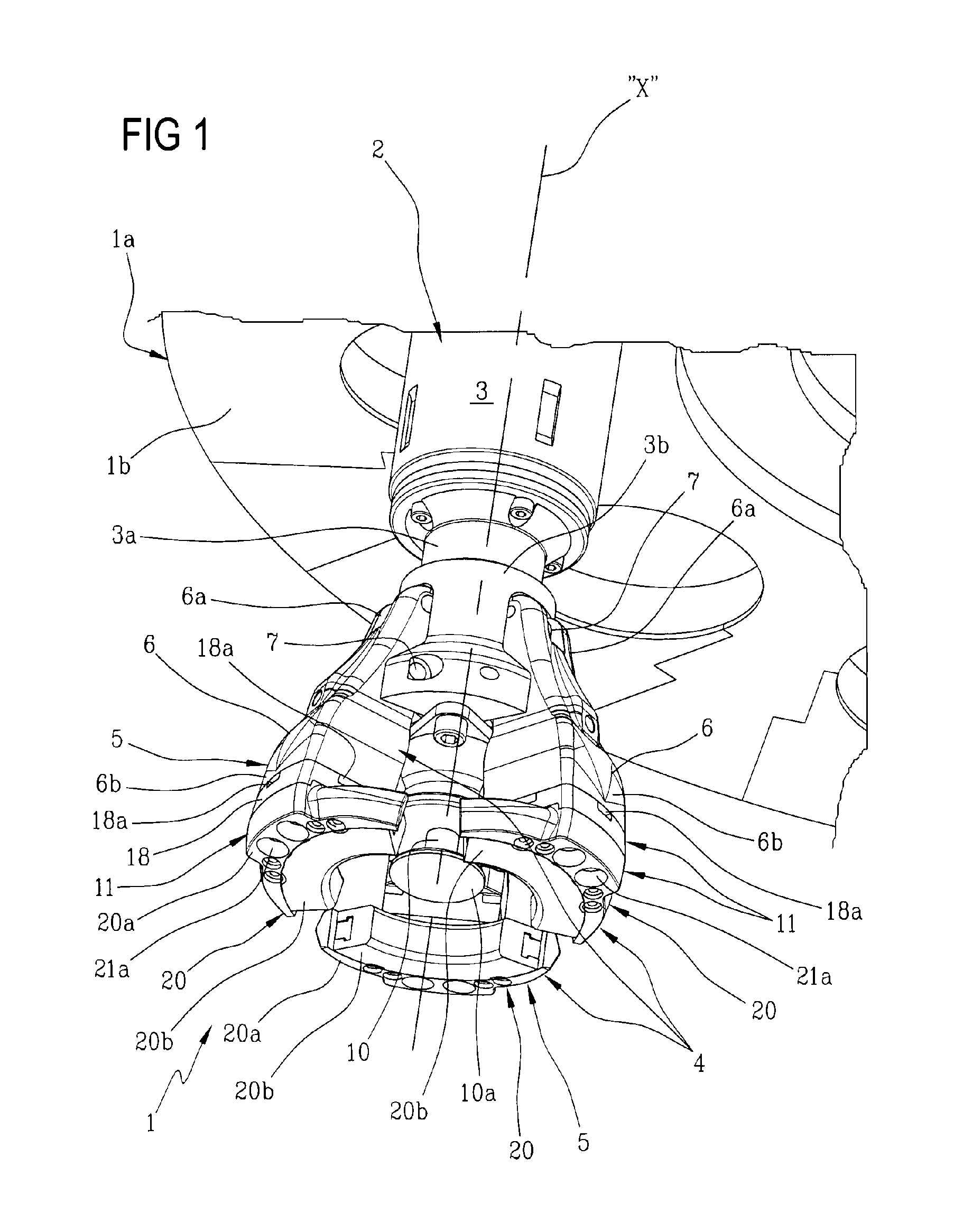
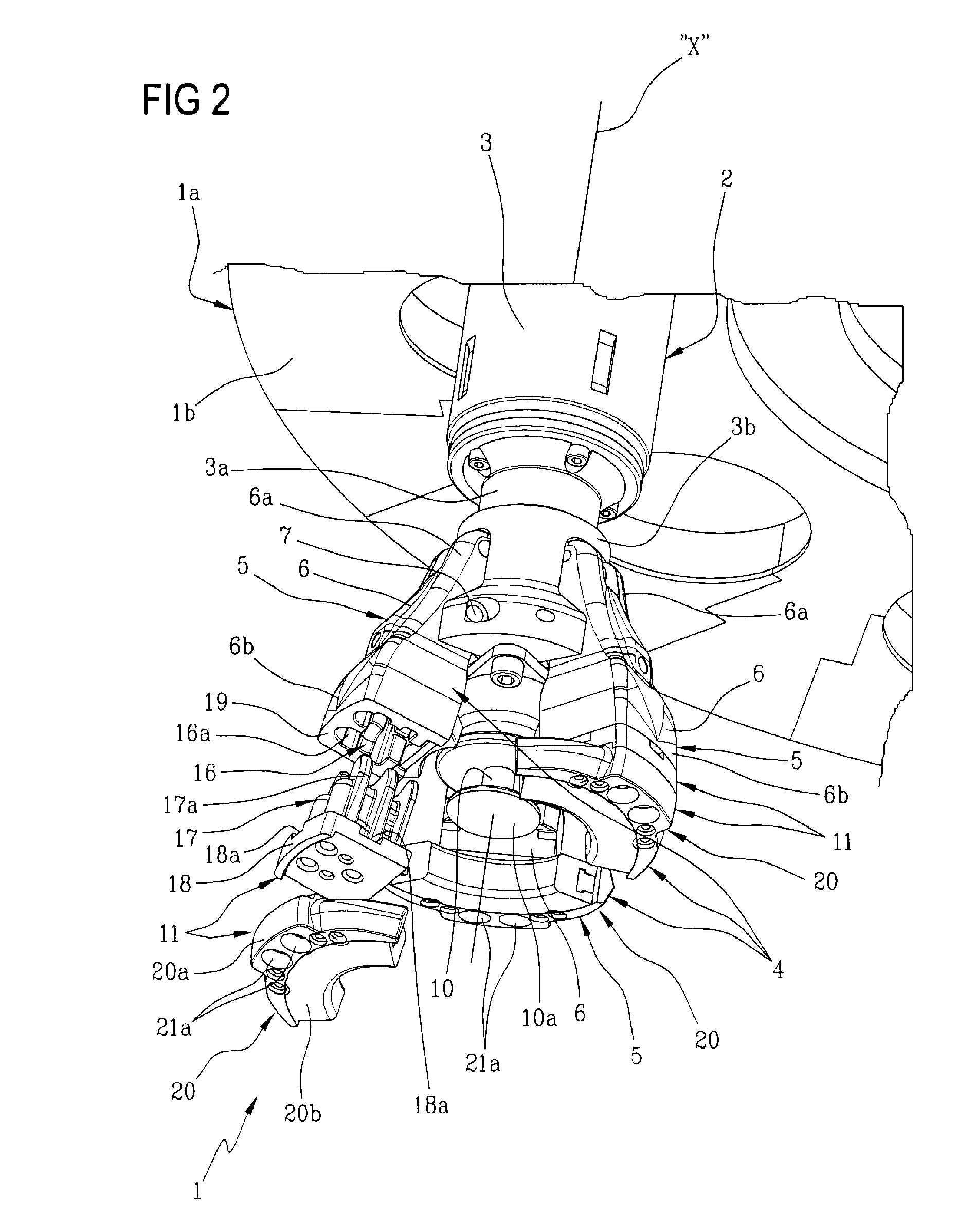
[0029]With reference to the figures of the accompanying drawings, the present invention relates to a gripping apparatus for capping assemblies, denoted 1 in its entirety, of the type fitted to the capping units of machines for packaging containers, in particular.

[0030]Generally speaking, containers designed to hold products of varying description, for example liquid, viscous, creamy, gelatinous and / or powdered substances, are filled and closed on machines (not illustrated, being conventional in embodiment) equipped with at least one capping unit 1a, indicated fragmentarily in FIGS. 1 and 2, by which caps or tops (not illustrated) are fitted automatically to respective containers (not illustrated) ready for closing.

[0031]Such capping units 1a are equipped normally with a plurality of capping assemblies 2 (FIGS. 1, 2 and 4), mounted peripherally to supporting structures or carousels 1b, indicated fragmentarily in FIGS. 1 and 2, and arranged in a circumferential ring centred on a prefe...


PUM


Abstract

Capping assemblies (2) of the type fitted to capping units (1a) in a machine for packaging containers filled with fluid or powdered products are equipped with a gripping apparatus (1) comprising a gripper (4) with three arms (5), each carrying an adapter (20) furnished with a pad (20b) offered in direct contact to the cap, through which the gripping action is applied. Each adapter (20) is secured to a fitting (17, 18) insertable into a socket (16) afforded by the bottom of a structural member (6) that forms the main part of each arm (5) and is hinged to the movable head of a relative capping assembly (2); when inserted into the structural member (6), the fitting (17, 18) is retained automatically by a snap lock mechanism (12) incorporated into the arm (5), which can be released subsequently by introducing the tip of a screwdriver into a slot (18a) created in the side of the fitting (17, 18) and levering the components apart.

Description

CROSS-REFERENCE TO RELATED APPLICATIONS[0001]This application is the National Phase of International Application PCT / IB2008 / 002062 filed Jul. 30, 2008 which designated the U.S. and that International Application was published under PCT Article 21(2) in English.[0002]This application claims priority to Italian Patent Application No. BO2007A000546 filed Aug. 2, 2007, and PCT Application No. PCT / IB2008 / 002062 filed Jul. 30, 2008, which applications are incorporated by reference herein.TECHNICAL FIELD[0003]The present invention relates to a gripping apparatus for capping assemblies, and in particular, an assembly of the type utilized in the capping units of machines for packaging containers.[0004]In particular, the present invention finds application in the packaging of containers designed to hold substances and / or products of liquid, viscous, creamy, gelatinous and / or powder consistency.BACKGROUND ART[0005]Conventionally, caps are applied automatically to respective containers by machi...

Claims


Application Information

Patent Timeline
Patent Type & Authority Applications(United States)
IPC IPC(8): B65B7/28B67B3/20
CPCB65B7/2835B65B59/04B67B3/2066B67B2201/10
Inventor ZANINI, GIANPIETROBARONI, MARCO
Owner AZIONARIA CONSTR MASCH AUTOMATICHE A C M A SPA
Why Eureka
Try Eureka