
Device for Delivering Medicament

a technology for delivering devices and medicaments, which is applied in the direction of medical atomisers, intravenous devices, other medical devices, etc., and can solve the problems of large devices that are not handled as easily, substantial risk of cartridge damage, and large risk of cartridge damag

Active Publication Date: 2010-07-29
SHL MEDICAL AG
View PDF5 Cites 40 Cited by
  • Summary
  • Abstract
  • Description
  • Claims
  • Application Information

AI Technical Summary

Benefits of technology

[0021]The present invention also substantially lowers the risk of damaging the cartridge and / or the device during medicament delivery in comparison with prior art automatic liquid medicament delivery devices.
[0022]The inventive delivery device also substantially improves the dose and the dose-to-dose accuracy in comparison with prior art devices.
[0023]With the present invention it also possible to set the predetermined dose that is to be delivered in an easy and reliable way.
[0024]Another object of the present invention is to provide an automatic liquid medicament delivery device, which substantially reduces the problems with creep in and plastic deformation of the plastic materials of the delivery device.
[0031]a plunger rod driving member engaged to the threaded plunger rod and adapted to be in a driven state when the device is in the medicament delivery state and adapted to be in a non-driven state when the device is in the medicament non-delivery state, wherein the rotation of the plunger rod driving member due to the output torque of energy accumulating member drives the threaded plunger rod and allows said rod which is in contact with the piston, to be driven towards the proximal end of the cartridge with a predetermined distance and expels a predetermined dose of the liquid medicament from the cartridge; wherein a bearing coupled to or supported on an outer cover is arranged and designed to effectively pick up forces acting on the proximal part of the device in the longitudinal direction thereof; whereby more of the accumulated energy that results from the stepwise rotational tensioning of the energy accumulating member positioned at the distal end of the device, is brought to an efficient output torque.
[0033]Moreover, according to another aspect of the present invention, there is provided a device for delivery of predetermined doses of liquid medicament wherein a cartridge housing is coupled to the outer cover and wherein the interior part of the cartridge housing engaging the plunger rod is provided with means engages longitudinal extending means on the plunger rod and wherein the interior part of the plunger rod driving member engaging the plunger rod is provided with a thread that corresponds to the thread on the plunger rod, so that the rotation of the plunger rod driving member will drive the plunger rod towards the proximal end of the cartridge the predetermined distance without rotation.

Problems solved by technology

However, the conventional cartridge is often made of an easily breakable material, such as glass, and having an initial high force acting on the piston will result in that there is a substantial risk of damaging the cartridge, which is most undesirable.
One can generally say that when a plunger rod is allowed to freely act on the piston, there is a substantial risk of damaging the cartridge when the piston is applied with a force that is above or equal to approximately 50-60 N.
However, a smaller spring constant would require a larger spring and hence a larger device.
A larger device is generally not handled as easily as a device with a smaller size.
Another problem is, that there is a minimum force value required to initially act on the piston in order for the piston to start the movement from its original position in the distal end of the cartridge, which minimum force in the art often is referred to as the “break loose force”.
This force would not be obtained if the device was provided with a spring having a too small spring constant.
This is undesirable, especially when the medicament is to be inhaled by the patient.
This phenomena also results in that the rate with which the medicament is delivered may differ from one dose to another, since a higher dose requires an initially higher force to act on the piston than a lower dose, i.e. the so called “dose-to-dose accuracy” is poor with prior art automatic delivery devices.
Moreover, the conventional cartridge does not always have a smooth interior surface but may exhibit irregularities or unevenness as a result from the manufacturing procedure or as a result from the lubrication procedure, since the interior of the conventional cartridge most often is lubricated before use, for instance by the use of silicon oil.
Such an irregularity or unevenness may increase the travel resistance acting on the piston which may cause the piston to slow down or even get stuck before it has reached its predetermined position inside the cartridge, especially if the irregularity is to be found towards the end of the distance that the piston is required to travel when the force acting on it has declined to a low value.
Another problem is that the conventional delivery devices are generally made of plastic material due to manufacturing and economical reasons.
Having a pre-tensed spring provided in the interior of such a device, results in that the tension caused by the pre-tensed spring, is held back by means of plastic components, which can lead to creep and hence plastic deformation of the plastic materials.
This may reduce the life of the device and affect its accuracy and may also affect the automatic delivery function of said device.
Also, having a high force acting on the piston during medicament delivery can cause damage of the plastic components of the device, which thus is another reason why it is not suitable to have a too high force applied to the piston, besides the risk of damaging the cartridge.
However, this pen syringe does not offer neither the opportunity to cancel a set dose, so if a dose once set is not wanted for injection the only way to bring the syringe back in its neutral position is to spill the dose.
With syringes by which large doses may be set or in case the medicine is very expensive, as is the case with growth hormone, this is not acceptable.
Moreover, the device is not provided with means in order to set a predetermined dose of medicament to be delivered.
However, this injection device does not offer the opportunity to cancel a dose or the opportunity to accumulate more energy in order to deliver a large dose or predetermined doses at multiple injection sites.
Moreover, the device has the torsion rods positioned alongside of the cartridge, which is not favourable in the case when a torsion rod breaks, since said break can damage the cartridge.
Further, none of the above mentioned documents mention how to bring more of a spring force to an efficient output torque.

Method used


Image

  • Device for Delivering Medicament
  • Device for Delivering Medicament
  • Device for Delivering Medicament

Examples


first embodiment

The Delivery Device of the Present Invention

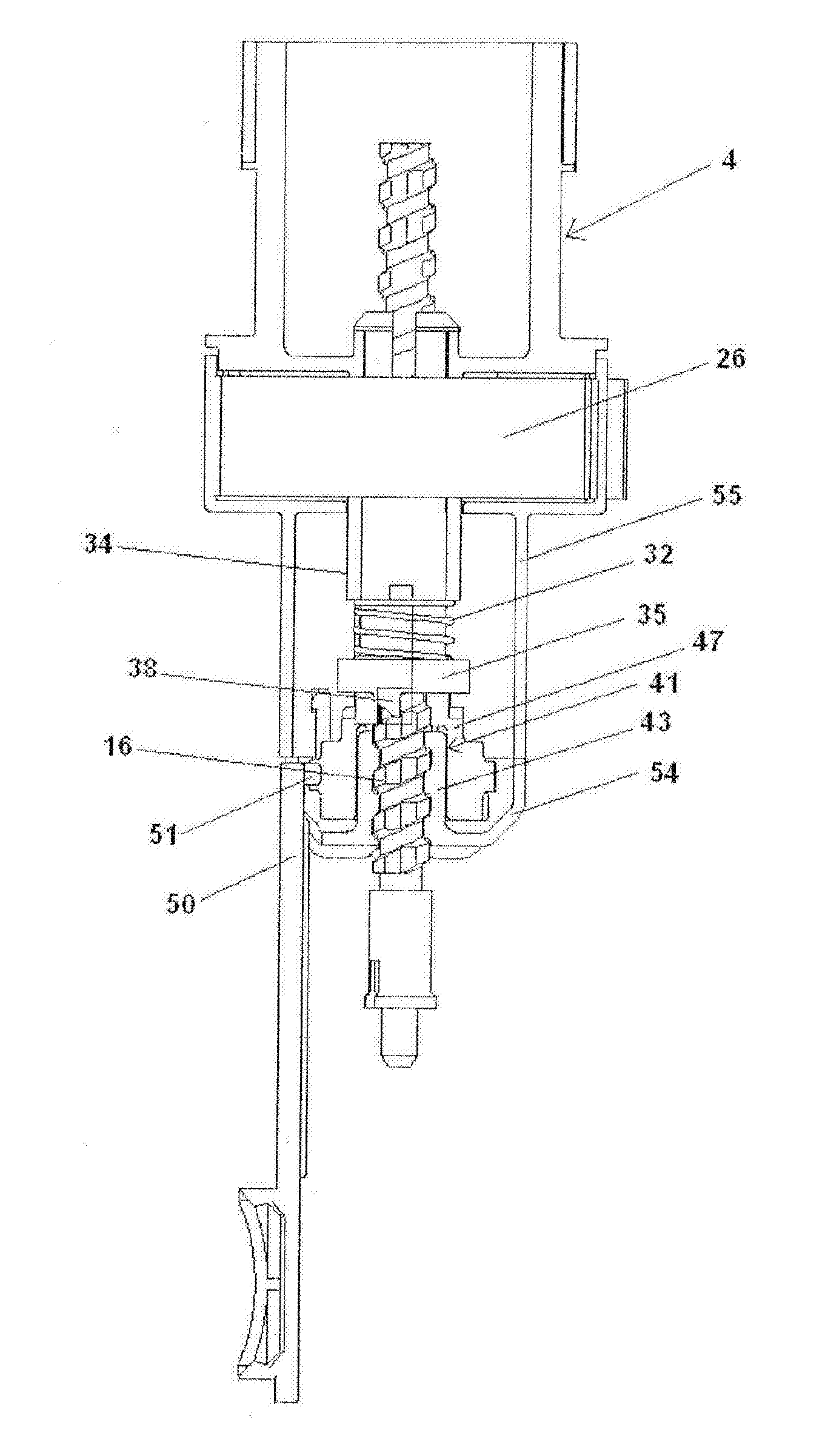
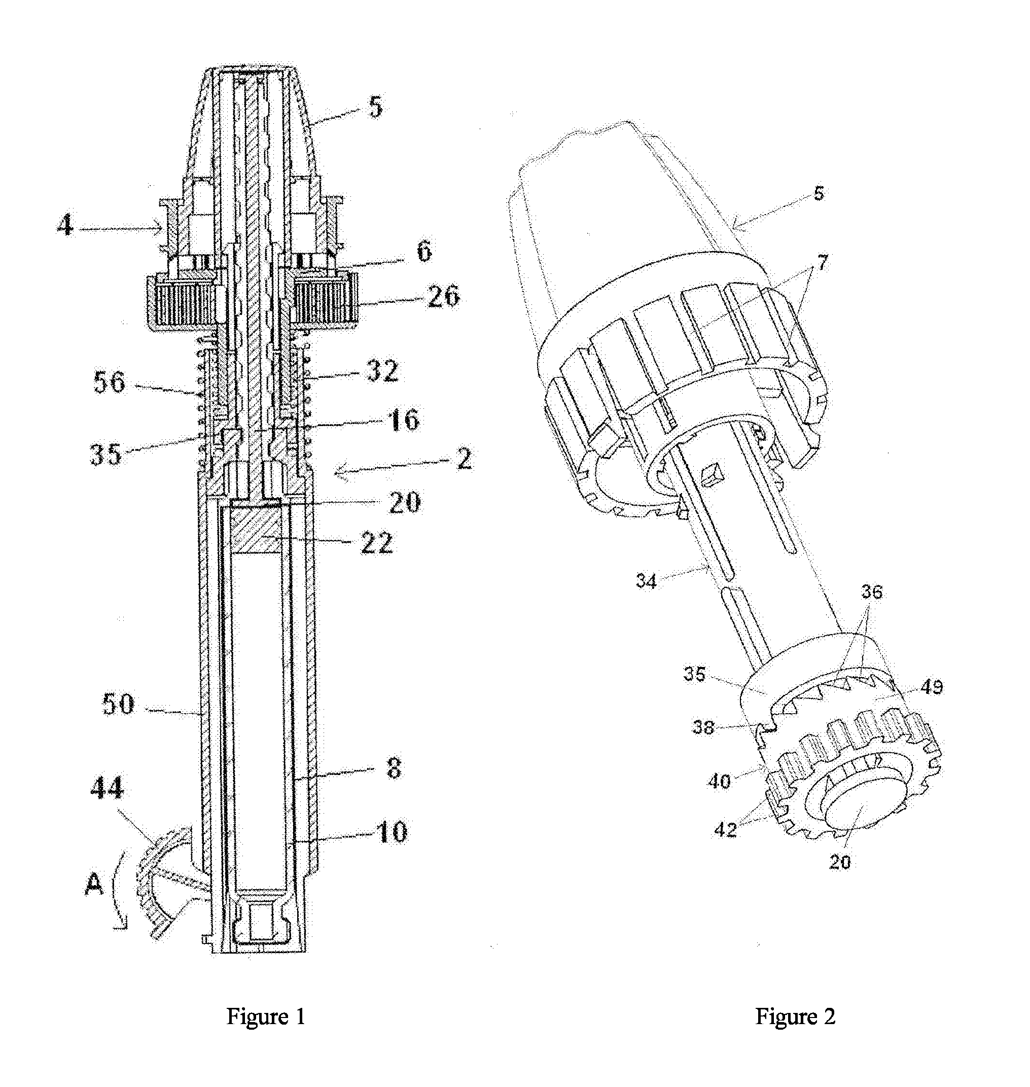
[0063]FIGS. 1-6 refer to a configuration of the delivery device wherein the plunger rod is adapted to be in a non-rotating state during medicament delivery. The delivery device 2 comprises in its distal end a dose setting member in the form of a dose wheel 4 and in its proximal end a cartridge housing 8, coupled to an outer cover 48, comprising a cartridge 10. The cartridge 10 is intended to be filled with the liquid medicament to be administered to the patient and the delivery device is thus provided with means in order to be connected to a suitable medicament administrating member, provided with corresponding means (not shown). The medicament administrating member is preferably a mouth or nasal piece, which the patient puts in his mouth or nose, respectively, whereby a metered dose of medicament is inhaled by the patient when the delivery device is set in a medicament delivery state, which will be described in further detail below. The m...

second embodiment

The Delivery Device of the Present Invention

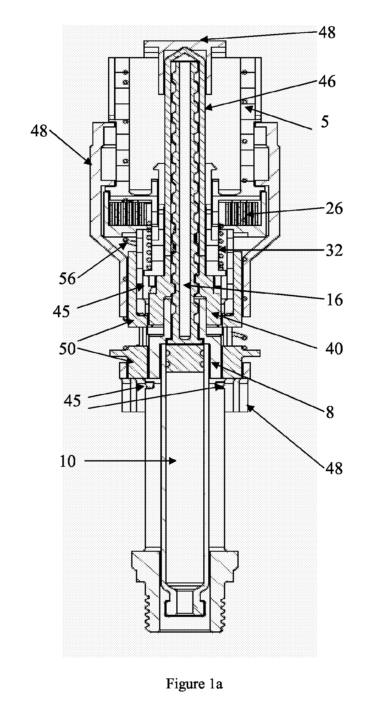
[0096]The delivery device 100 of the second embodiment, shown in FIGS. 10-14, comprises in its proximal part a cartridge housing 101, coupled to an outer cover 108, comprising a cartridge 103, as seen in FIG. 10. The cartridge 103 is intended to be filled with the liquid medicament to be administered to the patient and the delivery device is thus provided with means in order to be connected to a suitable medicament administrating member, provided with corresponding means (not shown). The medicament administrating member is in the second embodiment of the present invention preferably a needle for the injection of a liquid medicament into the body of the patient, wherein the liquid can have a low as well a high viscosity, but may also be for instance be a mouth or nasal piece, which the patient puts in his mouth or nose, respectively, whereby a metered dose of medicament is inhaled by the patient when the delivery device is set in a medicame...


PUM


Abstract

The present invention relates to a device for the delivery of predetermined doses of liquid medicament to a patient, which medicament is intended to be inhaled by the patient or intended to be injected into the body of the patient. The device is adapted to be in a medicament delivery state and in a medicament non-delivery state. When the device is in a medicament delivery state, said device is adapted to drive a piston into a cartridge containing the liquid medicament to be delivered, with a force that is above or equal to a predetermined minimum force value and below a predetermined maximum force value. The minimum force value is the lowest force value needed to deliver the predetermined dose and the maximum force value is the first force value at which it exists a risk of damaging the cartridge or the components of the device. Further, more of the spring force is brought to an efficient output torque ensuring that a predetermined volume of medicament is expelled from a cartridge.

Description

TECHNICAL FIELD[0001]The present invention relates to a device for the delivery of predetermined doses of liquid medicament to a patient, which medicament is intended to be inhaled by the patient or intended to be injected into the body of the patient. The device is adapted to be in a medicament delivery state and in a medicament non-delivery state. When the device is in a medicament delivery state, said device is adapted to drive a piston into a cartridge containing the liquid medicament to be delivered, with a predetermined force value. Said force is preferably above or equal to a predetermined minimum force value and below a predetermined maximum force value.BACKGROUND ART[0002]The development of devices for delivering liquid medicament to a patient, have during the recent years become more and more directed towards the ability for the patient themselves to administer the medicament with a predetermined dose in an easy, safe and reliable way and also to facilitate the administrat...

Claims


Application Information

Patent Timeline
Patent Type & Authority Applications(United States)
IPC IPC(8): A61M5/20A61M15/00A61F9/00A61M35/00
CPCA61M5/20A61M5/24A61M5/2448A61M5/3146A61M5/31535A61M5/31551A61M5/31553A61M5/31556A61M5/3156A61M5/31573A61M5/31583A61M5/31593A61M5/484A61M15/0045A61M15/0065A61M15/0091A61M2005/2013A61M2005/3125A61M2205/585A61M2005/202A61M15/0066A61M15/0073A61M15/0076A61M15/0081A61M15/0083A61M2202/0468A61M2210/0618A61M2210/0625A61M2210/0612A61M11/007A61M15/08A61M2205/8281
Inventor KRONESTEDT, VICTORBRUNNBERG, LENNARTOLSON, STEPHANDEURRELL, TOMASKARLSSON, ANDERS
Owner SHL MEDICAL AG
Learn More