
Haemodialfiltration method and apparatus

a technology of haemodiafiltration and apparatus, which is applied in the direction of filtration separation, multi-stage water/sewage treatment, separation process, etc., can solve the problems of increased viscosity, poor flow, and concentrated blood in the haemofilter, so as to prolong the service life of the haemofilter and avoid the effect of reducing the performance of the sam

Inactive Publication Date: 2010-07-29
FUNDACION PARA LA INVESTIGACION BIOMEDICA DEL HOSPITAL GREGORIO MARANON
View PDF4 Cites 52 Cited by
  • Summary
  • Abstract
  • Description
  • Claims
  • Application Information

AI Technical Summary

Benefits of technology

[0003]The aforementioned device comprises two circuits; a dialysis liquid is connected to a first circuit through the external chamber of a haemofilter against the direction of the blood flow, which is connected to a second circuit to maximize the difference in concentration of the substances that one wishes to remove, in all areas of the filter.
[0010]A consequence of the above is that the performance of ultra-filtering decreases and an increase occurs in the resistance to the path of the blood flow, which may lead to a poor flow and the clotting of the second blood circuit; since the rate of haemofiltration rises, the blood becomes concentrated in the haemofilter, its viscosity increases and the hydraulic resistance and risk of clotting of the same increases.
[0011]A consequence of the above is that the service life of the haemofilter is reduced.CHARACTERIZATION OF THE INVENTION
[0013]A purpose of this invention is to extend the service life of the haemofilter and avoid the decreased performance of the same during its effective lifetime.
[0014]Another purpose of this invention is to decrease the risk of blood clotting in the second blood circuit of the haemodiafiltration device.
[0015]Yet another purpose of this invention is to decrease the risk of obstruction of the filtering media, the semipermeable membrane, which separates the two flows that enter and leave the haemofilter.

Problems solved by technology

However, this method has some disadvantages, such as the blood in the haemofilter becoming very concentrated when a high amount of liquid is extracted.
A consequence of the above is that the performance of ultra-filtering decreases and an increase occurs in the resistance to the path of the blood flow, which may lead to a poor flow and the clotting of the second blood circuit; since the rate of haemofiltration rises, the blood becomes concentrated in the haemofilter, its viscosity increases and the hydraulic resistance and risk of clotting of the same increases.

Method used


Image

  • Haemodialfiltration method and apparatus
  • Haemodialfiltration method and apparatus
  • Haemodialfiltration method and apparatus

Examples


Embodiment Construction

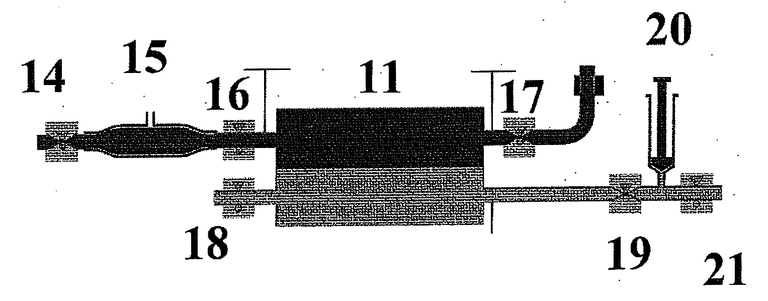
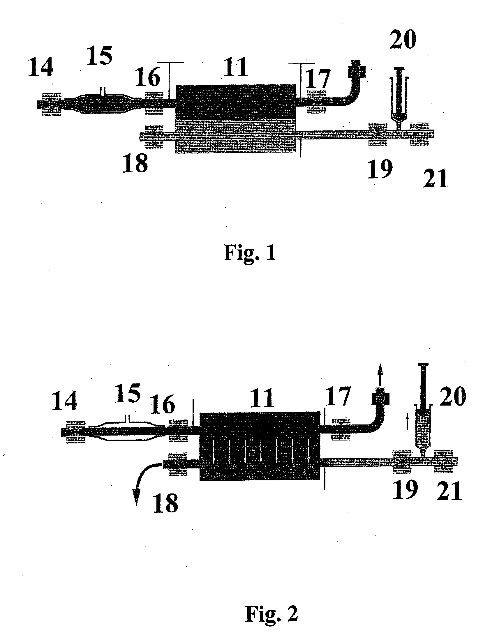
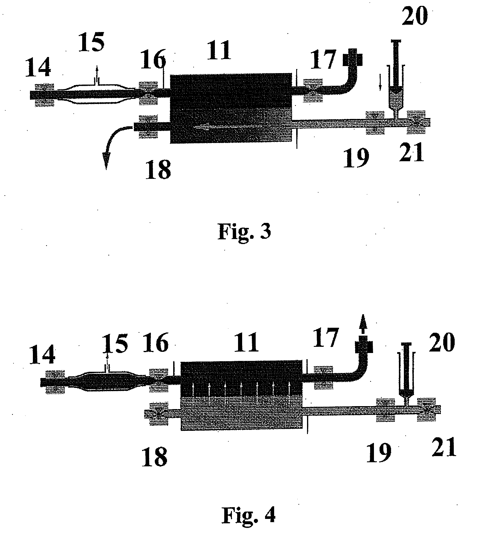
[0021]In reference to FIG. 1, below there is a flow chart schematically illustrated of a device used to perform haemodiafiltration, which comprises a first circuit of the dialysis solution regulated by the action of a first set of valves 18, 19, 21 and a pump 20 just like a syringe tube pump 20, which is located upstream of the first dialysis circuit, i.e. before a haemofilter 11.

[0022]A second regulated blood circuit, also regulated by the action of a second set of valves 14, 16, 17 and a pump 15, just like a tube pump 15, which is located on the upstream side, i.e. the arterial side of the second blood circuit before the haemofilter 11.

[0023]Both the first and second circuit come into contact at the haemofilter 11, which comprises a semipermeable membrane.

[0024]As has been mentioned previously, each circuit comprises at least three valves 18, 19, 21, 14, 16 and 17, respectively, distributed upstream and downstream of haemofilter 11.

[0025]Replacement liquid is injected through syri...


PUM

PropertyMeasurementUnit
molecular weightaaaaaaaaaa
concentrationaaaaaaaaaa
resistanceaaaaaaaaaa

Abstract

Device for haemodiafiltration, which comprises a first circuit for a dialysis solution and a second circuit for blood, so that the toxic substances from the blood flow pass into the dialysis liquid within a haemofilter (11), a liquid pump (20) located upstream of the haemofilter (11) in the first dialysis liquid circuit, is adapted for injecting replacement liquid into the dialysis solution flow after a blood pump (15) finishes pumping blood to the interior of the haemofilter (11).

Description

PURPOSE OF THE INVENTION[0001]This invention refers to a method and device for performing haemodiafiltration, which is a renal dialysis method that combines haemodialysis and haemofiltration, in order to achieve a high removal of substances with a high and low molecular weight.STATUS OF THE TECHNIQUE[0002]From patent EP0516152B1, a device is known for performing haemodiafiltration, namely, an extra-renal purification technique that combines two mechanisms: dialysis or diffusion and ultrafiltration or convection.[0003]The aforementioned device comprises two circuits; a dialysis liquid is connected to a first circuit through the external chamber of a haemofilter against the direction of the blood flow, which is connected to a second circuit to maximize the difference in concentration of the substances that one wishes to remove, in all areas of the filter.[0004]Therefore, a dialysis liquid is infused into the haemofilter against the flow, which will be removed with the ultra-filtering....

Claims


Application Information

Patent Timeline
Patent Type & Authority Applications(United States)
IPC IPC(8): B01D61/26B01D61/28B01D61/32
CPCA61M1/1037A61M1/3427A61M1/3441A61M60/113A61M60/851
Inventor DEL CANIZO LOPEZ, JUAN FRANCISCO
Owner FUNDACION PARA LA INVESTIGACION BIOMEDICA DEL HOSPITAL GREGORIO MARANON
Learn More