System and method for broaching a workpiece

a workpiece and system technology, applied in the field of system and method for broaching workpieces, can solve the problems of undesirable amount of floor space in a manufacturing facility used for the machine, the disadvantage of conventional systems, and the large size of machines

Inactive Publication Date: 2010-07-29
FEDERAL BROACH HLDG
View PDF11 Cites 3 Cited by
  • Summary
  • Abstract
  • Description
  • Claims
  • Application Information

AI Technical Summary

Benefits of technology

[0020]The method yet still further includes mounting, by the robot, a first sub-bar of the plurality of sub-bars onto the ram of the broaching machine, wherein the first sub-bar has a first broaching tool removably mounted thereon. The method further includes performing, by the broaching machine, a broaching operation on the workpiece using the first broaching tool. Finally, the method still further includes affixing a second broaching tool to a second sub-bar of the plurality of sub-bars simultaneous to the performance of the broaching operation. In another exemplary embodiment, rather than or in addition to affixing a second broaching tool to a second sub-bar, the method includes moving, by the robot, a sub-bar other than the first sub-bar to a storage location simultaneous with the performance of the broaching operation.

Problems solved by technology

These conventional systems are not without their disadvantages, however.
For one, these machines are typically very large and therefore have a very large footprint.
As a result, an undesirable amount of floor space in a manufacturing facility is used for the machine.
Further, because three broaching tools, and therefore, three rows of teeth, are mounted to the ram, the ram is rendered undesirably large.
Another disadvantage is due to the required change-out or replacement of the broaching tools.
More particularly, when the broaching tools have to be changed, the machine is down for an extended and undesirable period of time.
As a result, the time for the overall manufacturing process is undesirably long.
Yet another disadvantage common with conventional broaching machines is the complexity resulting from having to move various parts of the machine along or about various axes.
Accordingly, machines such as that described above have four axes of motion, thereby rendering the machine undesirably complex.
Yet still another disadvantage lies in the lack of error proofing with respect to the broaching tools and / or corresponding tool segments being mounted to the ram in the proper sequence or order, and being mounted in the correct positions.

Method used


Image

  • System and method for broaching a workpiece
  • System and method for broaching a workpiece
  • System and method for broaching a workpiece

Examples


Embodiment Construction

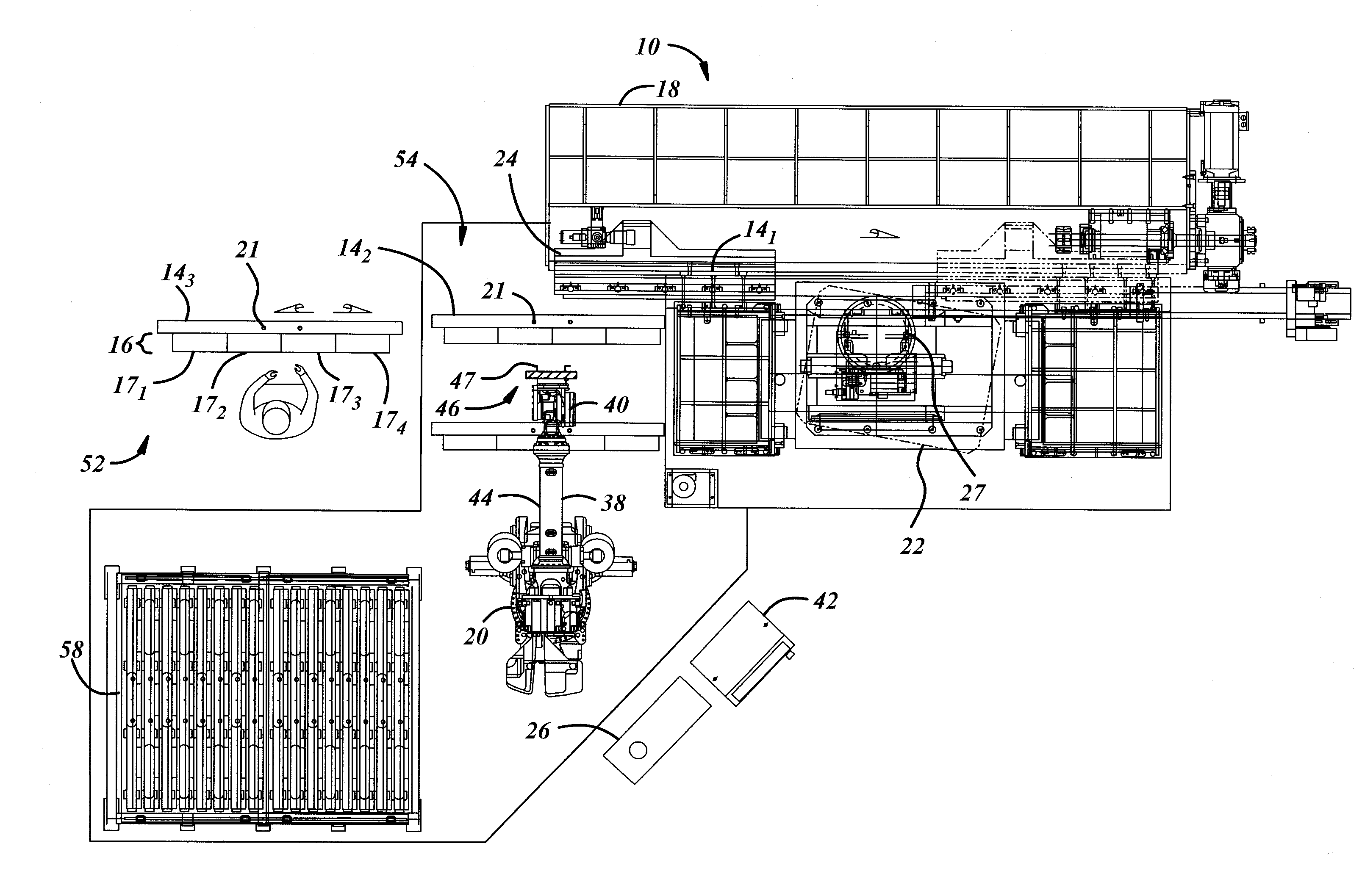
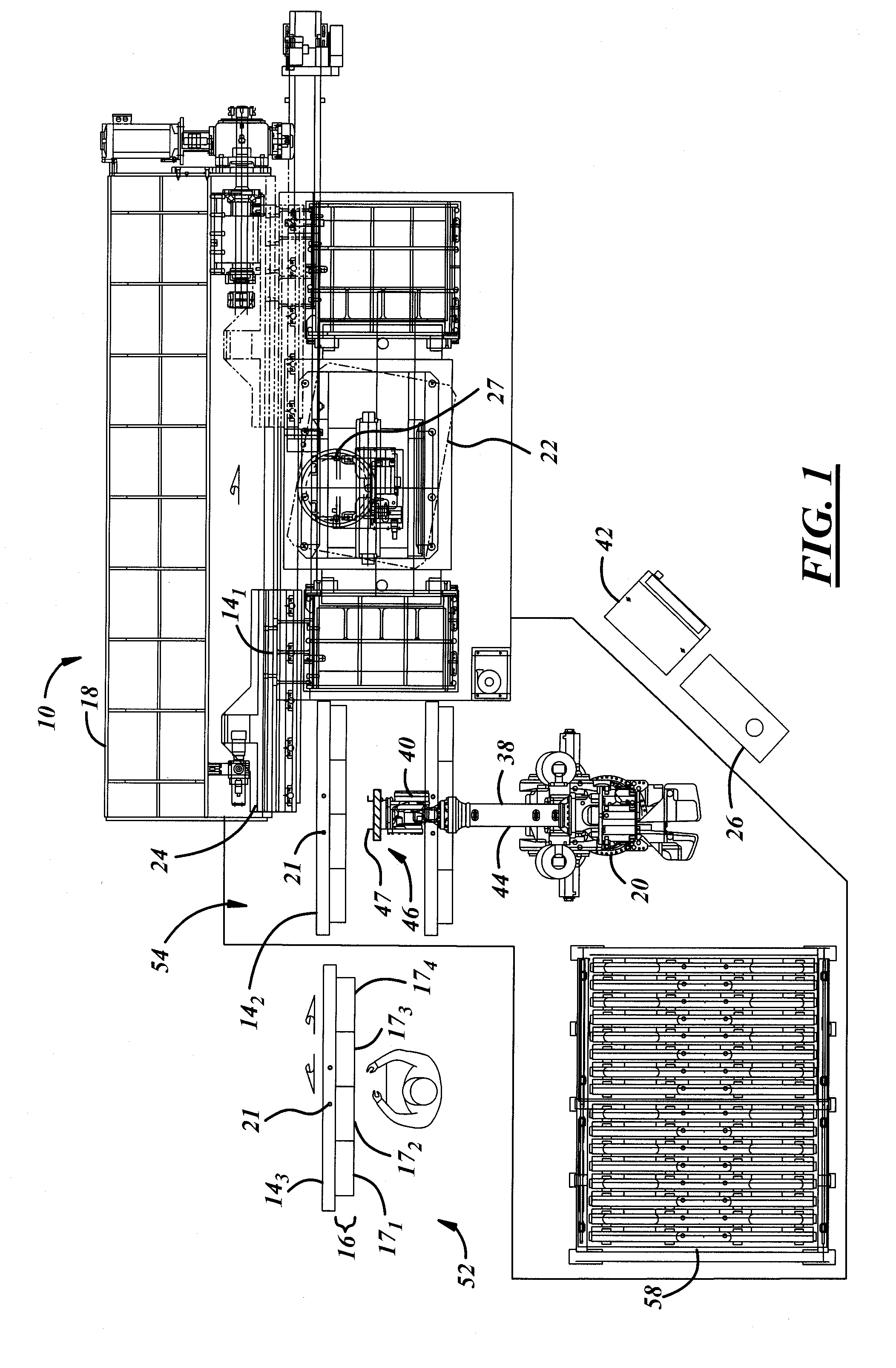
[0026]Referring now to the drawings wherein like reference numerals are used to identify identical components in the various views, FIG. 1 illustrates an exemplary embodiment of a broaching system 10 for broaching a workpiece 12, such as, for example and without limitation, a turbine disc. In an exemplary embodiment, the system 10 comprises a plurality of sub-bars 14 (141, 142, 143, . . . , 14N) each configured to receive a broaching tool 16, a broaching machine 18, and a robot 20. In the exemplary embodiment to be described in greater detail below, the broaching system 10 is configured to perform a horizontal broaching process on the workpiece 12. It will be understood, however, that the present invention is not meant to be so limited. Rather, those having ordinary skill in the art will appreciate that the broaching system 10, and the methodology performed thereby, may find application in other types of broaching processes, such as, for example, vertical broaching processes.

[0027]W...


PUM

PropertyMeasurementUnit
areaaaaaaaaaaa
areaaaaaaaaaaa
lengthaaaaaaaaaa

Abstract

A broaching system comprises a plurality of sub-bars configured to receive broaching tools. The system further comprises a broaching machine and a robot, the robot being configured to mount and remove sub-bars from the broaching machine. The robot includes an arm operable in three or more axes, and an end of arm tool. A method of broaching comprises providing a plurality of sub-bars, a broaching machine, and a robot having an arm operable in three or more axes and an end of arm tool. The method further includes mounting, by the robot, a sub-bar onto the broaching machine; and performing a broaching operation using the sub-bar. Simultaneous to the performance of the broaching operation, the method includes affixing another tool to another sub-bar, and/or moving, by the robot, another sub-bar to a storage location.

Description

CROSS REFERENCE TO RELATED APPLICATIONS[0001]This application claims the benefit of U.S. Provisional Patent Application Ser. No. 61 / 146,897 filed Jan. 23, 2009 and entitled “Broach Machine Apparatus,” which is incorporated herein by reference in its entirety.BACKGROUND OF THE INVENTION[0002]a. Field of the Invention[0003]The present disclosure relates to a system and method for broaching a workpiece, such as, for example, a turbine disc.[0004]b. Background Art[0005]Broaching, in general terms, is a precision machining process that employs cutting or broaching tools to progressively shave away material from a workpiece. Broaching finds application in the manufacture or fabrication of many different articles, and various machines for performing a variety of broaching processes are generally well known in the art.[0006]One exemplary article that lends itself to broaching is a turbine disc used, for example, in the power generation and aerospace fields. In practice, a turbine disc is mo...

Claims


Application Information

Patent Timeline
Patent Type & Authority Applications(United States)
IPC IPC(8): B23D37/00
CPCB23D37/06B23D39/00B23D41/00Y10T409/400175B25J11/00Y10T409/4077B23D2043/025
Inventor MARTIN, ROBERT M.WITER, JOSEPH H.BICKERSTETH, DANIEL T.ROTH, MICHAEL J.
Owner FEDERAL BROACH HLDG
Why Eureka
Try Eureka