Catheter and Introducer Needle Assembly with Needle Shield

a technology of introducer needle and catheter, which is applied in the direction of catheters, catheters, trocars, etc., can solve the problems of difficult use, exposed sharp distal tips, and still occuring needlesticks with contaminated introducer needles

Inactive Publication Date: 2010-07-29
BECTON DICKINSON & CO
View PDF2 Cites 84 Cited by
  • Summary
  • Abstract
  • Description
  • Claims
  • Application Information

AI Technical Summary

Benefits of technology

[0009]It is therefore an object of this invention to provide a needle shield that is compact.
[0010]It is another object of this invention to provide a needle shield that is simple and easy to use.

Problems solved by technology

Although clinicians are aware of the need to properly handle “blood contaminated sharps”, unfortunately in certain medical environments, such as emergency situations or as a result of inattention or neglect, needlesticks with a contaminated introducer needle still occur.
For example, some needle shields are bulky, difficult to use, require special features or techniques to be operative, or may leave the sharp distal tip exposed after use until the clinician manually activates the needle shielding mechanism.
Unfortunately, this configuration does not consistently ensure that the needle shield remains connected to the catheter hub until the introducer needle is locked in the needle shield.
This may be undesirable because the contaminated needle could then be exposed increasing the chances for an accidental needlestick.

Method used


Image

  • Catheter and Introducer Needle Assembly with Needle Shield
  • Catheter and Introducer Needle Assembly with Needle Shield
  • Catheter and Introducer Needle Assembly with Needle Shield

Examples


second embodiment

[0159]A second embodiment for the lock that prevents unwanted distal movement of introducer needle 31 is a leaf spring 200. See FIGS. 8 through 10. Leaf spring 200 has a proximal wall 210 defining an opening 215 therein aligned with proximal opening 43 of cavity 42. Proximal wall 210 is generally perpendicular to the longitudinal axis of introducer needle 31. Where enlarged diameter portion 38 is used on introducer needle 31, preferably opening 215 has a diameter at least slightly larger than the diameter of the main portion of introducer needle 31 but smaller than the diameter of enlarged diameter portion 38. Of course, it is not necessary for leaf spring 200 to include proximal wall 210 and opening 215 as long as proximal opening 43, washer 49 or tether 50 is used to prevent proximal movement of sharp distal tip 32 out of needle shield 40.

[0160]Leaf spring 200 also has a support leg 220 and a locking leg 230 oriented at an angle to support leg 220 such that locking leg 230 is dire...

third embodiment

[0164]A third embodiment for the lock that prevents unwanted distal movement of introducer needle 31 is a leaf spring 300. See FIGS. 11 through 13. Leaf spring 300 has a proximal wall 310 defining an opening 315 therein aligned with proximal opening 43 of cavity 42. Proximal wall 310 is generally perpendicular to the longitudinal axis of needle shield 40. Where enlarged diameter portion 38 is used on introducer needle 31, preferably the diameter of opening 315 is slightly larger than the diameter of the main portion of introducer needle 31 but smaller than the diameter of enlarged diameter portion 38. Of course, it is not necessary for leaf spring 300 to include proximal wall 310 and opening 315 as long as proximal opening 43, washer 49 or tether 50 is used to prevent proximal movement of sharp distal tip 32 out of needle shield 40.

[0165]Leaf spring 300 also has a support leg 320 and a locking leg 330 oriented at an angle to support leg 320 such that locking leg 330 is directed gene...

fourth embodiment

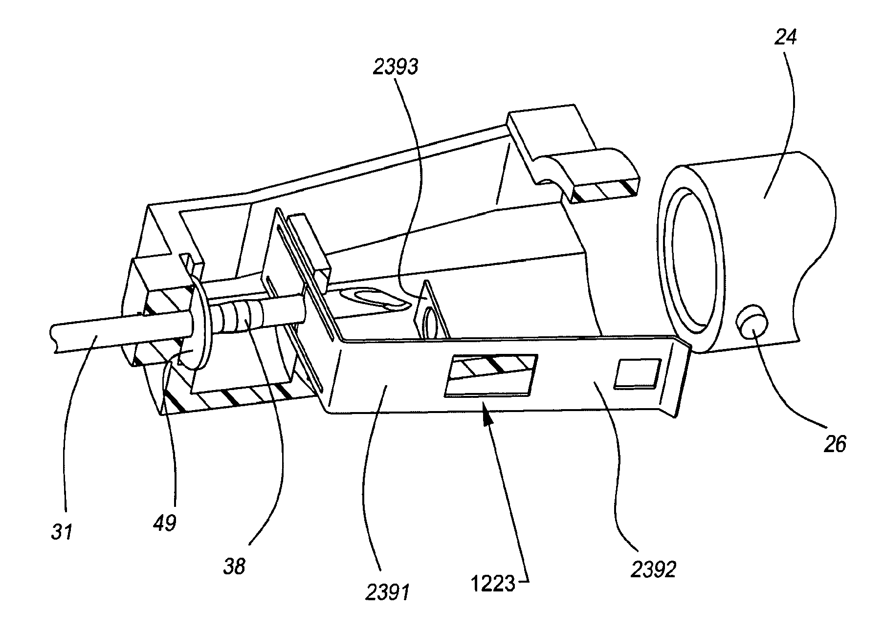
[0176]At least one, but preferably each support leg 520 includes a support finger 550 thereon. Each support finger 550 cooperates with a support tab 560 formed on housing 41 to hold each support leg 520 away from the shaft of introducer needle 31. Leaf spring 500 is disposed in cavity 42 such that proximal wall 510 is spaced distally from the proximal wall of cavity 42 to allow proximal movement of leaf spring 500 when introducer needle 31 is withdrawn into needle shield 40. When enlarged diameter portion 38 engages proximal wall 510 as a result of the proximal movement of introducer needle 31, leaf spring 500 will be moved proximally with continued proximal movement of introducer needle 31. This allows each support finger 550 to be moved out of engagement with support tabs 560, which in turn allows support legs 520 to return to their inward position. In the inward position, locking legs 530 engage the main portion of introducer needle 31. Unwanted distal and proximal movement of in...


PUM


Abstract

A catheter and introducer needle assembly with a needle shield is provided. The needle shield includes a means for preventing unwanted distal movement of the needle once the needle has been withdrawn into the needle shield. The needle shield also includes a means for connecting the needle shield to the catheter hub until the sharp distal tip of the introducer needle has been withdrawn into the needle shield. Thus, when the distal end of the introducer needle extends from the distal portion of the needle shield, the needle shield is connected to the catheter hub and when the sharp distal end of the introducer needle is withdrawn into the needle shield, the needle shield is disconnected from the catheter hub. At that point, the sharp needle tip is secured within the needle shield.

Description

[0001]This application is a divisional of application Ser. No. 10 / 756,577 filed on Jan. 13, 2004, which is a continuation of application Ser. No. 09 / 717,148 filed on Nov. 21, 2000, now U.S. Pat. No. 6,749,588, which is a continuation-in-part of application Ser. No. 09 / 590,600 filed Jun. 9, 2000, which is a continuation-in-part of application Ser. No. 09 / 312,335 filed May 14, 1999, now U.S. Pat. No. 6,379,333, which is a continuation-in-part of application Ser. No. 09 / 057,718 filed Apr. 9, 1998, now U.S. Pat. No. 6,004,294. Application Ser. No. 09 / 717,148 now U.S. Pat. No. 6,749,588, is also a continuation-in-part of application Ser. No. 09 / 499,331 filed Feb. 4, 2000, which is a continuation-in-part of application Ser. No. 09 / 312,335 filed May 14, 1999, now U.S. Pat. No. 6,379,333, which is a continuation-in-part of application Ser. No. 09 / 057,718 filed Apr. 9, 1998, now U.S. Pat. No. 6,004,294. Application Ser. No. 09 / 717,148 now U.S. Pat. No. 6,749,588, is also a continuation-in-pa...

Claims


Application Information

Patent Timeline
Patent Type & Authority Applications(United States)
IPC IPC(8): A61B17/34A61M25/06A61M5/32
CPCA61M5/3273A61M5/3275A61M2005/325A61M2005/3247A61M25/0625
Inventor HARDING, WESTON F.CINDRICH, CHRISTOPHER N.HOWELL, GLADE H.BRIMHALL, GREG L.THORESEN, STEPHEN L.
Owner BECTON DICKINSON & CO
Why Eureka
Try Eureka