Compressed air starter for turbomachine

a turbomachine and compressor technology, applied in the ignition of the engine/propulsion engine, engine starters, liquid fuel engines, etc., can solve the problems of generating impacts, limiting the risks of ingress of outside projectiles, and generating debris inside the turbine at high speed

Active Publication Date: 2010-08-05
SAFRAN POWER UNITS
View PDF6 Cites 12 Cited by
  • Summary
  • Abstract
  • Description
  • Claims
  • Application Information

AI Technical Summary

Problems solved by technology

Furthermore, the aft end of the forward casing and the forward end of the aft casing are usually connected by a cylindrical mesh, which limits the risks of ingress of outside projectiles into the exhaust flow path when stopped, and risks of the projection of debris outside the exhaust flow path when an incident occurs during operation.
In case of such an incident, debris could be projected inside the turbine at high speed and generate impacts at the forward casing that surrounds this turbine.
Due to the rotational movement of the turbine, this debris could transmit tangential forces to the forward casing in addition to radial forces, which could generate a torque transmitted to this forward casing, and the debris could thus break the arms connecting this forward casing to the aft casing, and break the outlet mesh if it is fixed to the ends of these casings, causing separation between the two casings of the starter.
However, a starter of this type has disadvantages.
Said structural elements must be made from a relatively heavy and / or expensive material.
Furthermore, in case of a turbine burst, these structural elements could transmit the torque induced by impacts of debris on the forward casing of the starter, to the aft casing of this starter, which could damage attachment means of this aft casing onto a turbomachine.

Method used


Image

  • Compressed air starter for turbomachine
  • Compressed air starter for turbomachine
  • Compressed air starter for turbomachine

Examples


first embodiment

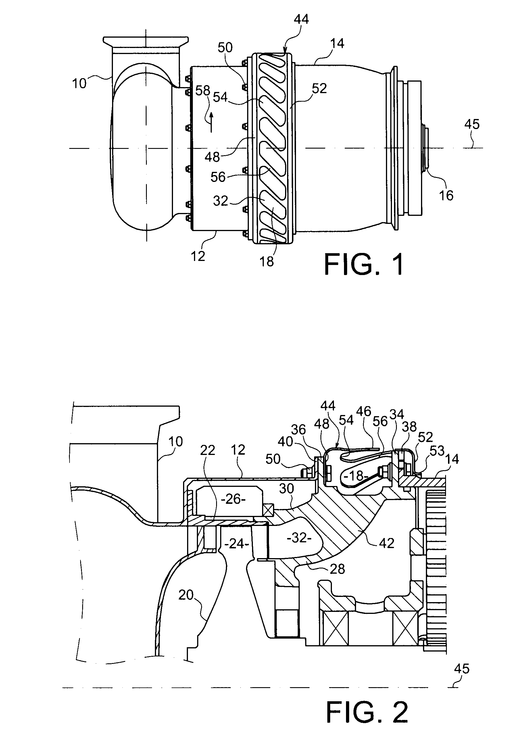
[0045]FIG. 1 shows an air starter conforming with the invention designed to be fitted on an aircraft turbojet.

[0046]This starter comprises an air inlet duct 10, an approximately cylindrical forward casing 12 surrounding a drive turbine, an approximately cylindrical aft casing 14 surrounding power transmission means, and means 16 of attaching the starter to an aircraft turbojet (not shown) and coupling the starter to an accessory gear box of this aircraft turbojet.

[0047]The air inlet duct 10 will be connected to a high pressure air source that can be onboard or on the ground.

[0048]The attachment and coupling means 16 are designed to fix the power transmission means and a rotor of the turbojet to each other in rotation, and to fix the starter to the turbojet.

[0049]During operation, the high pressure airflow supplying the turbine rotates a bladed wheel of this turbine, this bladed wheel in turn rotating the power transmission means that are connected to the turbojet rotor through coupl...

second embodiment

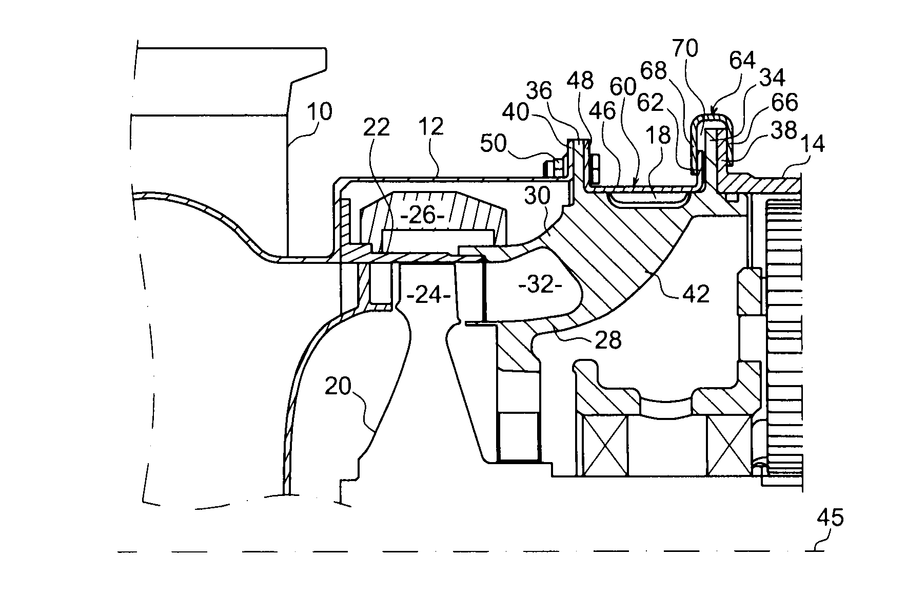
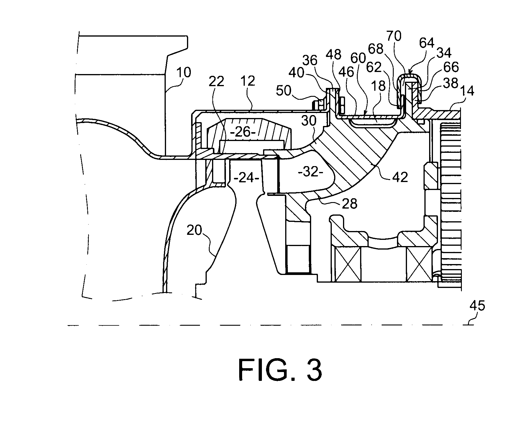
[0073]FIG. 3 shows an air starter according to the invention.

[0074]This starter comprises an outlet mesh 60 for the exhaust flow path 32 that is similar to the outlet mesh 44 of the starter described above, but which is different from this mesh 44 essentially in that the aft end part of the mesh 60 is radially curved towards the outside of the starter so as to form a radial wall 62 extending forwards from the radial flange 38 of the aft casing 14 of this starter.

[0075]This starter comprises a U-shaped annular part 64 that opens radially towards the inside of the starter and that is fixed onto the flange 34 of the annular envelope 28 delimiting the inside of the exhaust flow path 32, and onto the flange 38 of the forward end of the aft casing 14.

[0076]The annular part 64 has an aft radial wall that is fixed onto the flange 38 of the aft casing 14 by bolts (not shown in FIG. 3) or similar means, and a forward radial wall 68 that extends at an axial distance from the flange 34 of the e...


PUM


Abstract

Air starter for turbomachine, comprising a forward casing (12), an aft casing (14), an annular exhaust flow path (32) opening up between an aft end of the forward casing and a forward end of the aft casing, and a cylindrical outlet mesh (44) of the exhaust flow path (32) the forward and aft ends of which comprise means (48, 52) of axially retaining the forward casing (12) and the aft casing (14) respectively to the mesh (44), wherein at least said means (52) of axially retaining one (14) of the casings to the mesh (44) enable a relative rotation of the mesh (44) and this casing (14).

Description

TECHNICAL FIELD[0001]This invention relates to an air starter for a turbomachine, particularly such as a turbomachine for an aircraft.[0002]Turbomachine aircraft engines are usually equipped with air starters, comprising (from the forward towards the aft part) an air inlet duct, a turbine, and power transmission means that will be coupled to these engines, for example through an Accessory Gear Box (AGB) on these engines.[0003]When it is supplied with compressed air, the starter turbine will rotate the power transmission means which in turn will rotate a rotor of the turbomachine to start it.[0004]Air starters for aircraft engines are usually designed to start these engines on the ground, but also to restart them in flight if the engine should stall.[0005]Therefore, the reliability of air starters is of overriding importance for the safety of aircraft and to obtain the certifications necessary to use these starters.STATE OF PRIOR ART[0006]Air starters of a known type comprise a forwa...

Claims


Application Information

Patent Timeline
Patent Type & Authority Applications(United States)
IPC IPC(8): F02C7/27F04D29/52
CPCY02T50/671F02C7/277Y02T50/60
Inventor LE SAINT, RACHEL
Owner SAFRAN POWER UNITS
Why Eureka
Try Eureka