
Control device for a tattoo machine, and tattoo system

Inactive Publication Date: 2010-08-05
DUBIN WILLIAM
View PDF4 Cites 18 Cited by
  • Summary
  • Abstract
  • Description
  • Claims
  • Application Information

AI Technical Summary

Benefits of technology

[0040]One object of the embodiments of the present invention is to provide an astable multivibrator-triggered monostable multivibrator control device for a needle assembly of a tattoo machine, and for allowing an operator to selectively control frequency, length and force of a stroke of the needle assembly of the tattoo machine.
[0041]Another object of the embodiments of the present invention is to provide an astable multivibrator-triggered monostable multivibrator control device for a needle assembly of the tattoo machine, and for allowing an operator to selective control frequency, length, and force of a stroke of the needle assembly of the tattoo machine. The example control device includes an astable multivibrator and a monostable multivibrator. The astable multivibrator allows the operator to selectively control the frequency of the stroke of the needle assembly of the tattoo machine. The monostable multivibrator is triggered by the astable multivibrator and allows the operator to selectively control the pulse width of each cycle of the tattoo machine.

Problems solved by technology

Adjusting any variable mechanically affects the other parameters so it is difficult and arduous to adjust a machine optically by trial and error.
The contact points are often difficult to adjust and maintain in proper mechanical attunement, and the capacitor in the device periodically fails.
Additionally, in the conventional tattoo machine, operating parameters including frequency, i.e., number of needle strokes per unit of time, is difficult to control and alter with any precision because current affects both speed and magnetic strength of the coils simultaneously.
Although this basic design has been used successfully for many years, in practice it does have several problems.
Another significant problem is that it is difficult to adjust the machine mechanically so that it functions optimally.
This makes it difficult to get the mechanical adjustments just right.
In addition, it is very difficult to alter the frequency of a mechanically switched machine.

Method used


Image

  • Control device for a tattoo machine, and tattoo system
  • Control device for a tattoo machine, and tattoo system
  • Control device for a tattoo machine, and tattoo system

Examples


Embodiment Construction

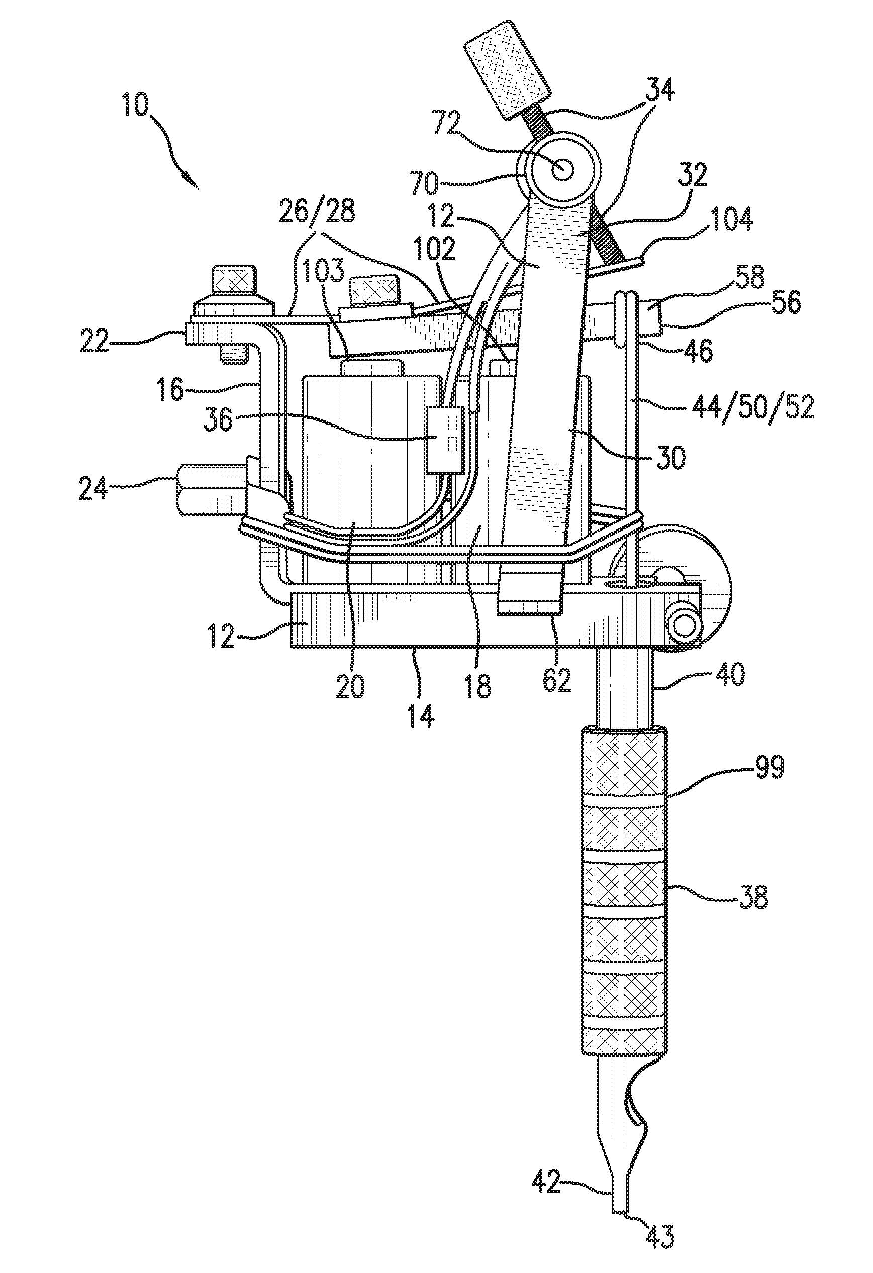
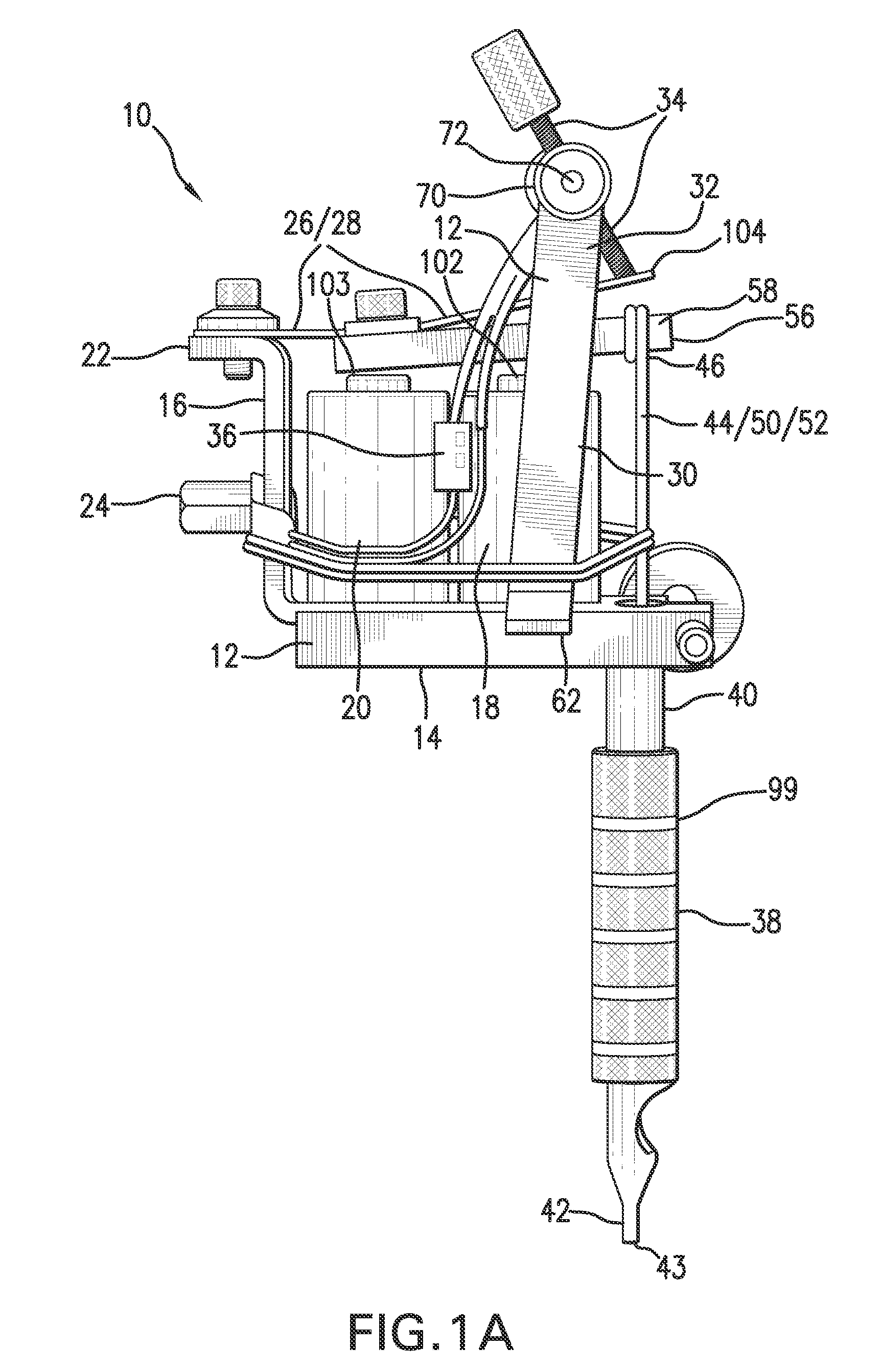
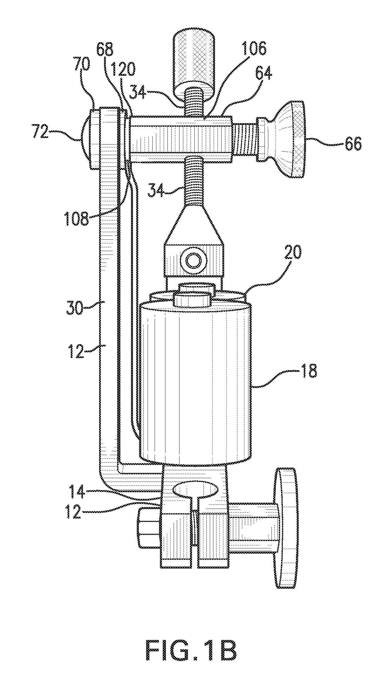
[0046]Electronic switching of the example embodiments of the present invention provides ease and flexibility while tuning the machine. There are several parameters that should be considered for proper machine functioning:

[0047]The stroke length should be long enough for the needles to move from being retracted into the tube where the needles can be coated with ink to being extended far enough to puncture the skin sufficiently to the desired depth.

[0048]Stroke frequency is difficult to alter on a mechanically switched machine. Frequency can be can be controlled with electronic circuitry that gates an electronic switch. Each machine tends to have an optimal frequency.

[0049]The actual stroke force that is delivered to the needle is a complex function of several variables, including, for example:[0050]how far the spring holds the armature above the coils in the resting position;[0051]spring stiffness;[0052]power delivered to the coil, which is a function of voltage, frequency, and duty ...


PUM


Abstract

A control device for a tattoo machine, and a tattoo system. The control device adapted to control reciprocation of a needle assembly of the tattoo machine using a pulsed signal. A duty cycle of the pulsed signal controlling a stroke length of the needle assembly. A frequency of the pulsed signal controlling a stroke frequency of the needle assembly. Duty cycle and frequency may be controlled independently of one another.

Description

CROSS REFERENCE[0001]The present application claims benefit under 35 U.S.C. §119 of U.S. Provisional Application No. 61 / 206,771, filed on Feb. 4, 2009, which is expressly incorporated herein by reference in its entirety.FIELD[0002]The embodiments of the present invention relate to a control device for a tattoo machine, and more particularly, the embodiments of the present invention relate to control of a tattoo machine using a pulsed signal. In one embodiment, an astable multivibrator-triggered monostable multivibrator control device is used to allow an operator to vary the relative percentage of time within a cycle that a tattoo machine is ON and OFF. The ON state, therefore, can be made longer or shorter compared to the amount of time the tattoo machine is in the OFF state within one cycle. The embodiments of the present invention also control the frequency of the cycles per second of the tattoo machine. Controlling the interaction among the frequency of strokes, the length of tim...

Claims


Application Information

Patent Timeline
IPC IPC(8): A61B17/34A61M37/00
CPCA61M37/0076
Inventor DUBIN, WILLIAM
Owner DUBIN WILLIAM
Learn More