Variable-displacement piston-cylinder device

a piston-cylinder device and variable displacement technology, applied in the direction of fluid couplings, rotary clutches, servomotors, etc., can solve the problems of high vibration resistance of conventional multi-cylinder piston-cylinder devices, and achieve the effect of reducing power output and fuel consumption

Inactive Publication Date: 2010-08-05
RIES JAMES D
View PDF47 Cites 10 Cited by
  • Summary
  • Abstract
  • Description
  • Claims
  • Application Information

AI Technical Summary

Benefits of technology

[0003]The present invention provides a variable-displacement stacked piston device that may be adapted for use in a combustion engine, a steam or air engine, a compressor, a pump, or the like. The piston-cylinder device defines two or more cylindrical expansion chambers between a “stacked” piston formed of piston members in a coaxial conjoined relationship, and a correspondingly-shaped cylinder, in which substantially any combination of the expansion chambers may be activated or deactivated in order to vary the effective displacement of the piston-cylinder device regardless of the total number of cylinders and pistons in the device. This arrangement may be particularly useful in combustion engines that operate with multiple cylinders, where known methods of shutting off one or more cylinders generally lead to vibration problems that must be addressed in other ways. The piston-cylinder device of the present invention is operable to selectively reduce the effective displacement of each piston-cylinder in mid-operation in order to reduce power output and fuel consumption (or pumping or compressing capacity), without introducing vibration. In addition, a control system is provided for managing the effective displacement of each piston-cylinder according to output required, desirable operating parameters, and other parameters that can effect the operation of the device.

Problems solved by technology

However, conventional multi-cylinder piston-cylinder devices are highly susceptible to vibration when less than all of the cylinders are operating due to unevenly-timed application of power strokes to the crankshaft as it rotates.

Method used


Image

  • Variable-displacement piston-cylinder device
  • Variable-displacement piston-cylinder device
  • Variable-displacement piston-cylinder device

Examples


Embodiment Construction

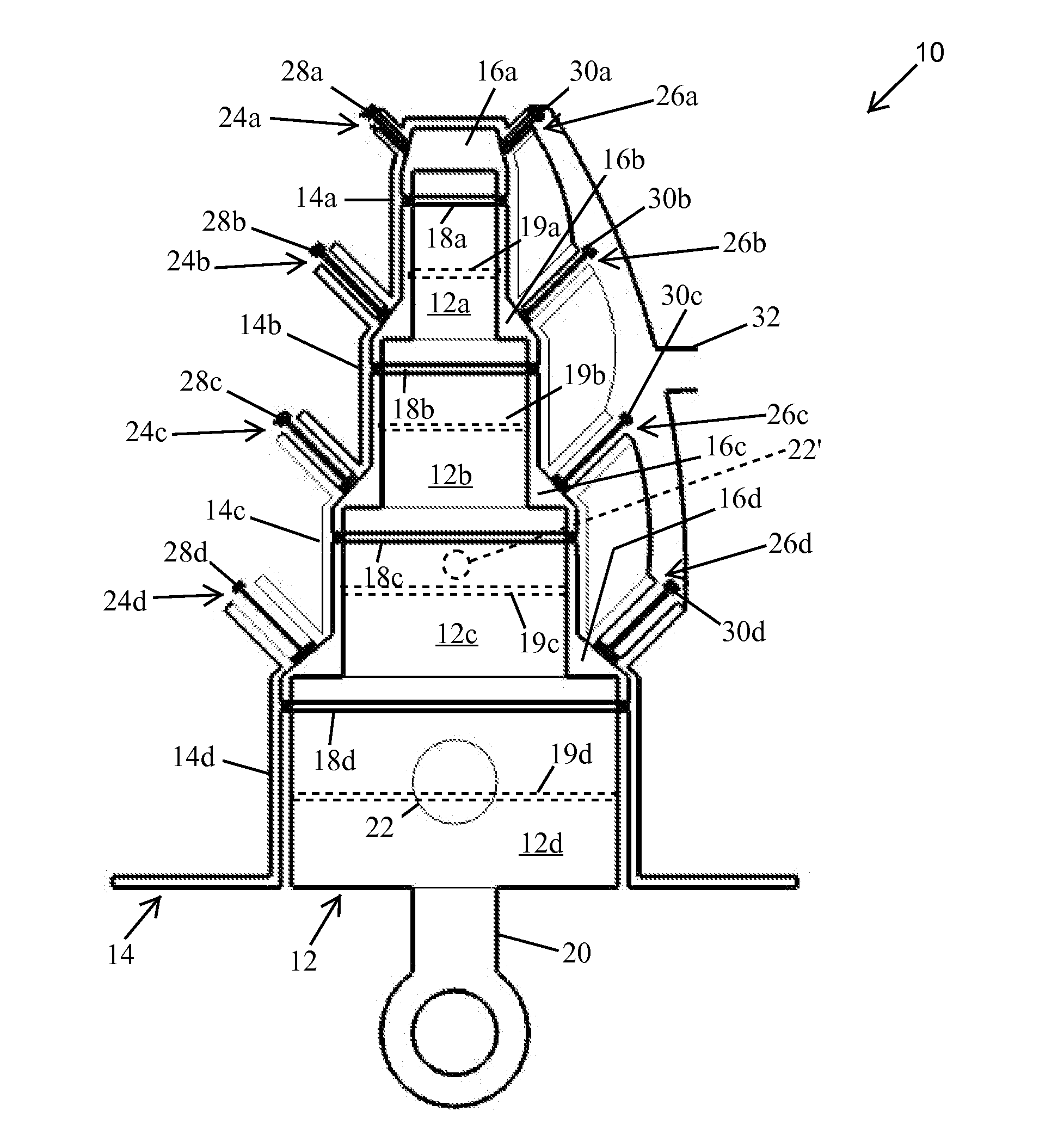
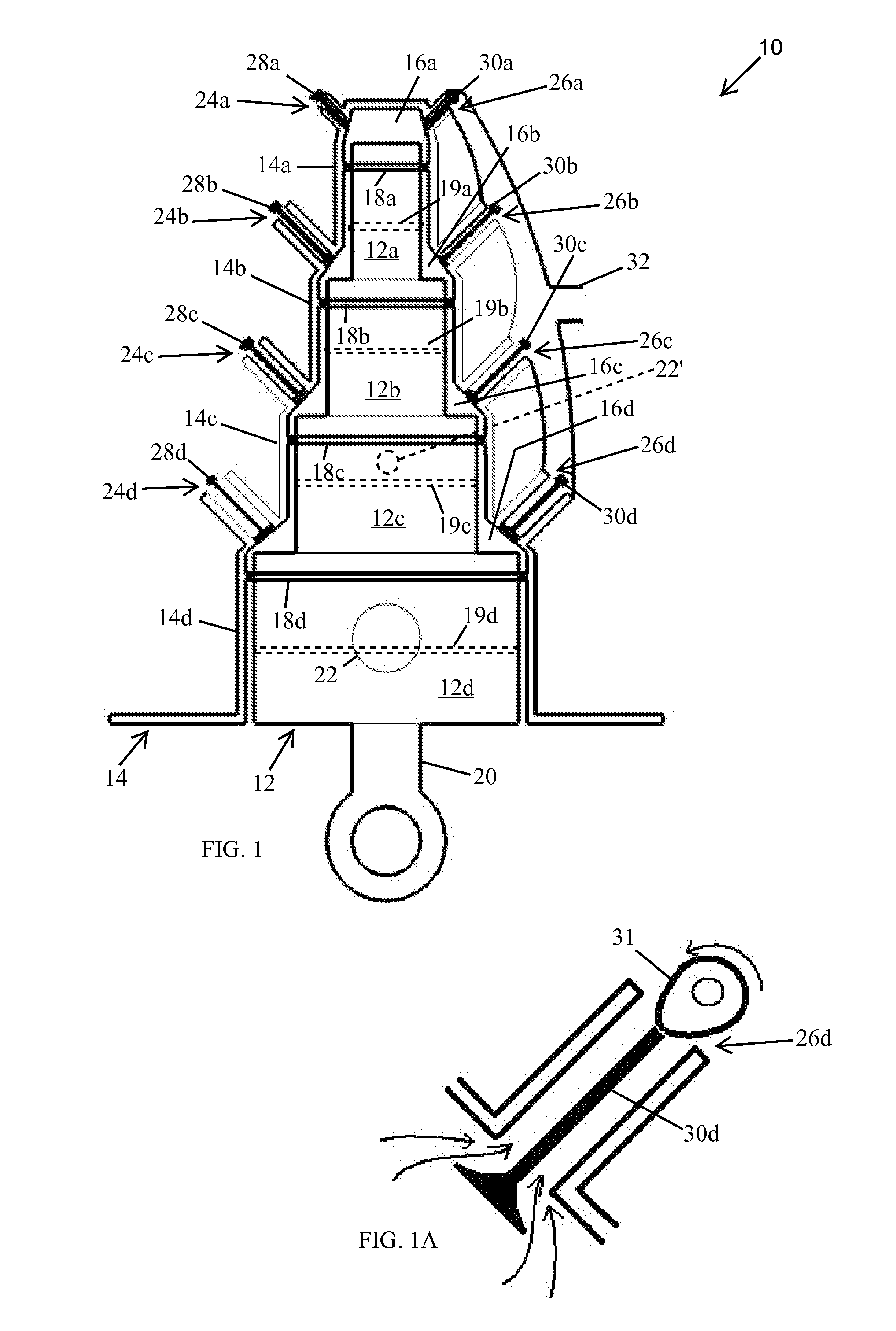
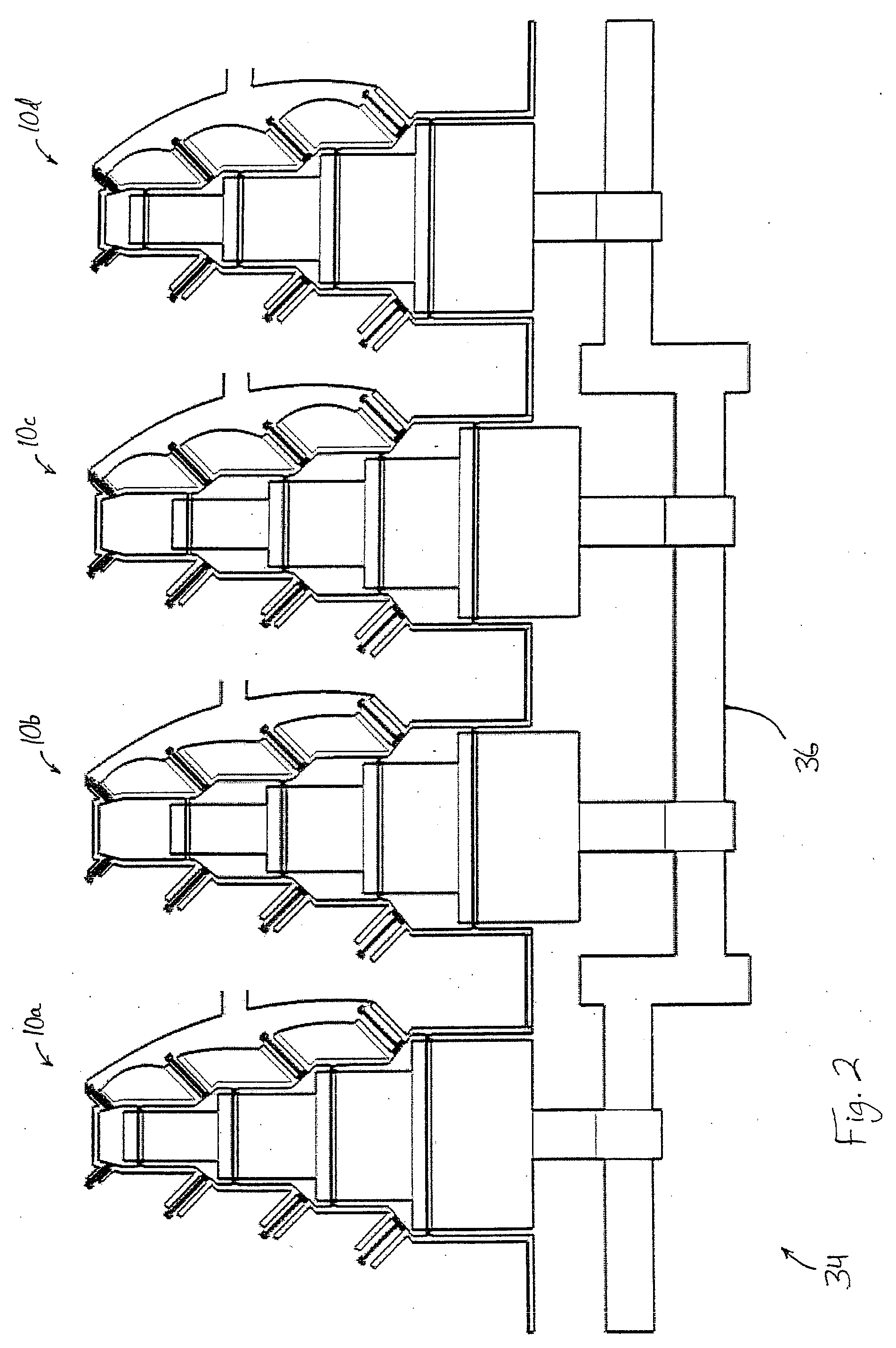
[0031]Referring now to the drawings and the illustrative embodiments depicted therein, a variable-displacement piston-cylinder device 10 provides variable-output capability for a single cylinder, such as for producing power, or for pumping or compressing fluids, or for performing a combination of those tasks, as will be described below. It will be understood that multiple piston-cylinder devices can be combined to provide a multi-cylinder device, such as that depicted in FIG. 2.

[0032]In the description that follows, it should be noted that the term “displacement” is used to refer to the volumetric differences of expansion chambers with piston members positioned between bottom dead center (BDC) and top dead center (TDC) in respective cylinder sections, while the term “effective displacement” is used to refer to the volumetric differences of only the activated expansion chambers.

[0033]Piston-cylinder device 10 includes a stacked piston 12 that is reciprocally received within a stacked...


PUM


Abstract

A variable-displacement piston-cylinder device may be adapted for providing work output, and/or for pumping or compressing fluids. The piston-cylinder device defines two or more coaxial cylindrical expansion chambers between a piston having two or more coaxial and conjoined piston members, and a correspondingly-shaped cylinder. Substantially any combination of the expansion chambers may be activated or deactivated in order to vary the effective displacement of the piston-cylinder device. The effective displacement of each piston-cylinder may be changed in mid-operation in order to reduce power output and fuel consumption (or pumping or compressing capacity), without introducing vibration. In addition, a control system is provided for managing the effective displacement of each piston-cylinder according to output required, desirable operating parameters, and other parameters that can effect the operation of the device.

Description

FIELD OF THE INVENTION[0001]The present invention relates generally to piston-cylinder devices, and in particular, to piston-cylinder devices for engine, pumping, and compressing applications.BACKGROUND OF THE INVENTION[0002]It is sometimes desirable to configure a piston-cylinder device, such as an internal combustion engine, so as to be operable at less than fall displacement capacity. For example, in automotive applications, it is known to configure eight-cylinder engines so that less than all eight cylinders are operable at any given time. However, conventional multi-cylinder piston-cylinder devices are highly susceptible to vibration when less than all of the cylinders are operating due to unevenly-timed application of power strokes to the crankshaft as it rotates.SUMMARY OF THE INVENTION[0003]The present invention provides a variable-displacement stacked piston device that may be adapted for use in a combustion engine, a steam or air engine, a compressor, a pump, or the like. ...

Claims


Application Information

Patent Timeline
Patent Type & Authority Applications(United States)
IPC IPC(8): F02B75/04
CPCF02B75/287F01B7/18
Inventor RIES, JAMES D.
Owner RIES JAMES D
Why Eureka
Try Eureka