
Combustion Apparatus

Active Publication Date: 2010-08-05
LANDY VENT UK
View PDF16 Cites 2 Cited by
  • Summary
  • Abstract
  • Description
  • Claims
  • Application Information

AI Technical Summary

Benefits of technology

[0010]We have found that using silicon carbide has a number of unexpected benefits. For example, we have found that the silicon carbide results in better and cleaner combustion.
[0046]According to a yet further aspect of the present invention, there is provided a method of increasing heat extraction from combustion apparatus for a solid fuel by providing baffling for secondary combustion of combustion products with air within a combustion chamber.

Problems solved by technology

As a result, heating is in the main only effective while solid fuel is being burned in the stove.

Method used


Image

  • Combustion Apparatus
  • Combustion Apparatus
  • Combustion Apparatus

Examples


Embodiment Construction

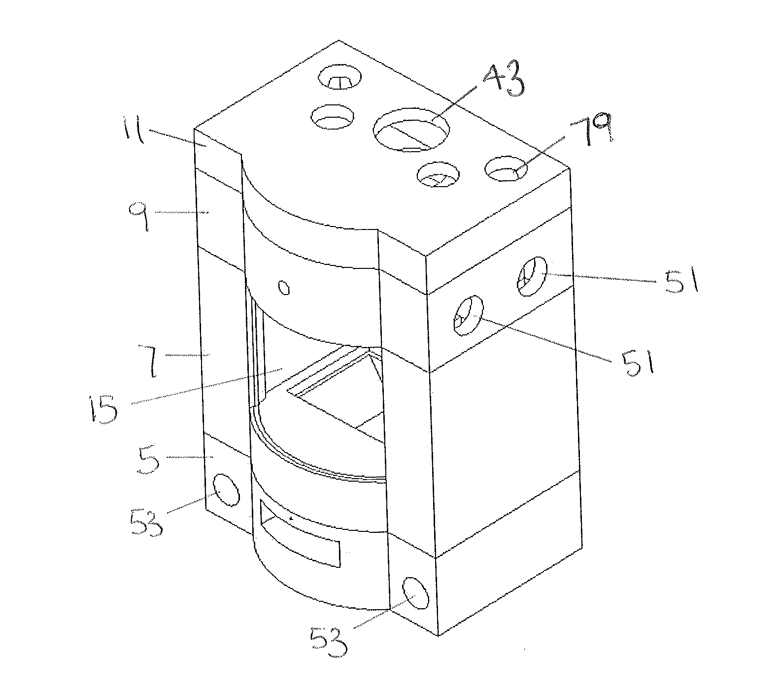
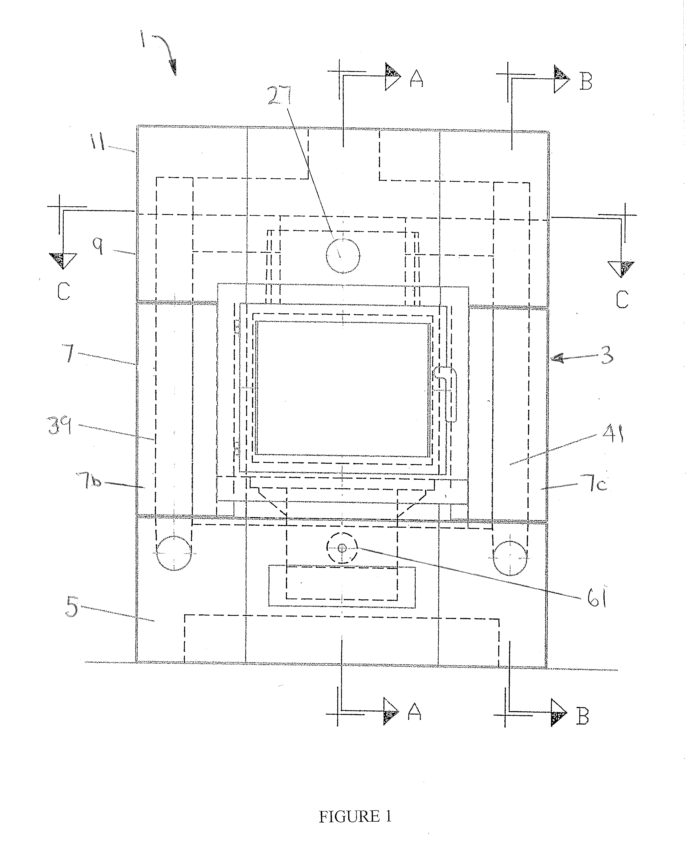
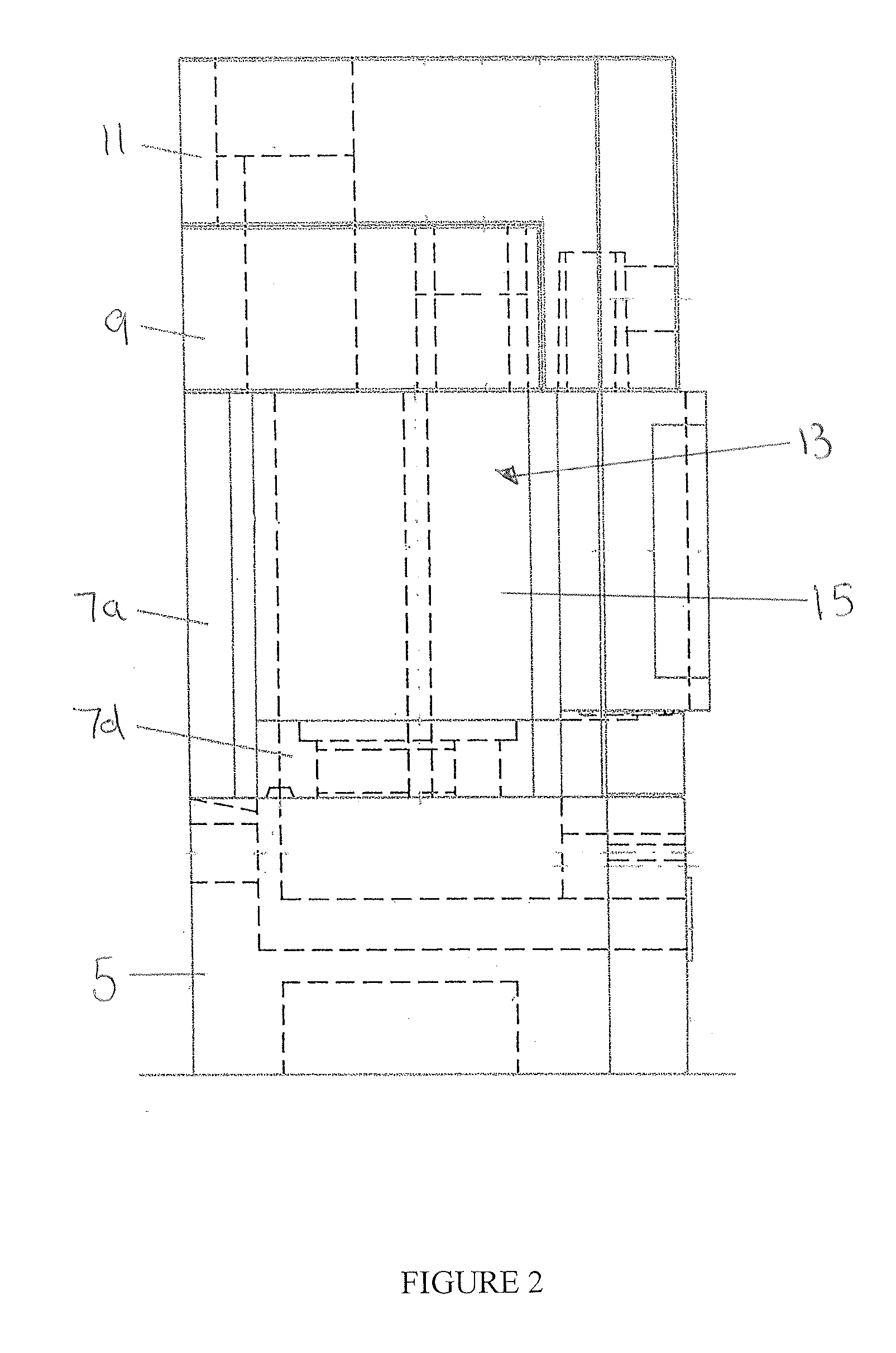
[0070]Referring first to FIGS. 1 to 7 of the drawings, there is shown combustion apparatus in accordance with the invention in the form of a stove 1 for use with a solid fuel such as wood, coal etc.

[0071]The stove 1 comprises a free standing body 3 constructed from blocks of a fired refractory material arranged in sections one on top of the other that are designated a base section 5, a lower intermediate section 7, an upper intermediate section 9 and a top section 11. The number of sections may vary according to the design of the stove 1.

[0072]In this embodiment, the base section 5, upper intermediate section 9 and top section 11 each comprise a single block although this is not essential and one or more of these sections may comprise a plurality of blocks. The lower intermediate section 7 comprises a plurality blocks assembled to provide a firebox 13 that defines a combustion chamber 15. The blocks include a rear block 7a, a pair of side blocks 7b, 7c and a base block 7d.

[0073]The...


PUM


Abstract

Combustion apparatus for use with a solid fuel has a firebox constructed at least in part of a fired refractory carbide material. The fired refractory carbide material has a catalytic effect on the combustion process providing a cleaner and more efficient combustion. The fired refractory material also absorbs heat from the combustion process directly or indirectly by heat exchange with combustion products and dissipates the absorbed heat over an extended period of time providing space heating after the combustion process is completed.

Description

CROSS-REFERENCE TO RELATED APPLICATIONS[0001]This application claims the benefit of Great Britain Patent Application Serial No. GB 0901688.2 filed on Jan. 31, 2009, and Great Britain Patent Application No. GB 0915318.0, filed Sep. 3, 2009.TECHNICAL FIELD OF THE INVENTION[0002]This invention relates to combustion apparatus for space heating. The invention has particular, but not exclusive, application to combustion apparatus for use with solid fuels including, but not limited to wood, coal and the like combustible materials.[0003]As used herein the term “solid fuel” includes natural fuel sources such as wood or coal and recycled fuel sources such as compressed blocks of sawdust and coaldust as well as other forms of substitute materials such as wood derived biomass fuel.BACKGROUND OF THE INVENTION[0004]In the known solid fuel stoves, combustible material is burned in a fire box to provide a heat source for heating the surrounding area by radiation from the body of the stove which is ...

Claims


Application Information

Patent Timeline
IPC IPC(8): F24C1/14F23J1/00F23B90/00
CPCF24B1/24F24B1/195F23M5/00F24B1/006F24B1/26F24B1/19
Inventor ASHMORE, DAVID OWEN
Owner LANDY VENT UK
Learn More