Method for manufacturing tubes by welding

a manufacturing method and tube technology, applied in the direction of mechanical equipment, chemistry equipment and processes, other domestic objects, etc., can solve the problems of deformation of the skirt, particularly prejudicious to the joining and tube-filing operation, and the production of flexible tubes

Active Publication Date: 2010-08-05
AISAPACK HLDG SA
View PDF3 Cites 4 Cited by
  • Summary
  • Abstract
  • Description
  • Claims
  • Application Information

AI Technical Summary

Benefits of technology

[0023]Advantageously, the deformation operation consists in increasing the area of the welded zone by an amount corresponding to the shrinkage of said zone due to the effect of the heating and cooling. This amount depends on

Problems solved by technology

One difficulty encountered when producing flexible tubes by welding lies in the deformation of the skirt during the welding operation.
These out-of-roundness defects are particularly prejudicial to the joining and tube-filing operations.
The operation of joining the skirt to the head by welding requires the head to be inserted into the skirt, which operation is all the more difficult the greater the out-of-roundness defect.
This operation is greatly disturbed when the cross section of the tube is not circular.
The out-of-roundness of the skirts has an influence on the final geometry of the tube and in many cases the out-of-roundness defects impair the aesthetic p

Method used


Image

  • Method for manufacturing tubes by welding
  • Method for manufacturing tubes by welding
  • Method for manufacturing tubes by welding

Examples


first embodiment

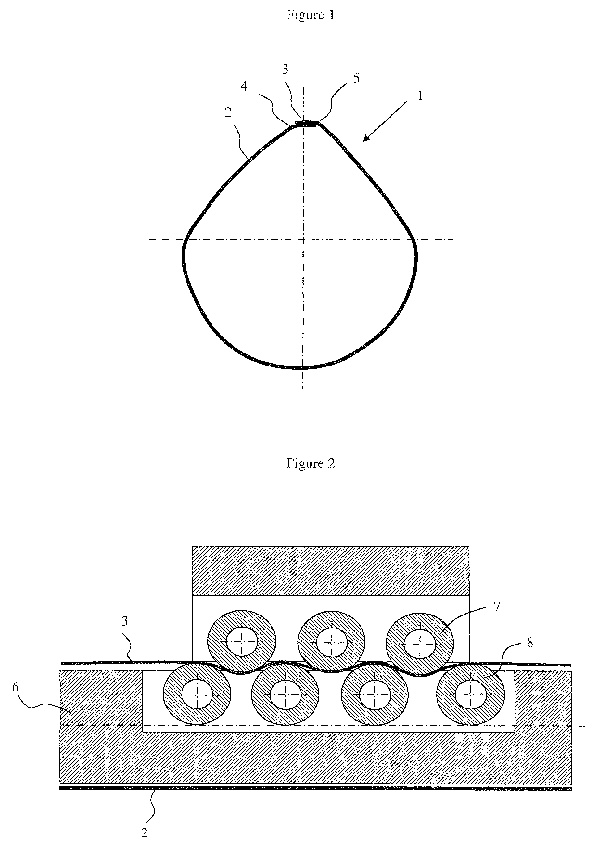
[0038]the invention consists of a welding method that includes an operation of elongating the welded zone in the longitudinal direction, i.e. in a direction perpendicular to the cross section of said tubular body. A first example for elongating the welded zone in a method in which the laminate moves at a constant speed over a welding rod, consists in varying the speed of the welding zone. This speed variation is obtained for example by means of a device made up of drive rollers located in the welding zone, the rotation speed differential of which has the effect of elongating the welded zone. A second example of the method and device for elongating the welded zone in the longitudinal direction is illustrated in FIG. 2. This device, inserted into a welding rod, is illustrated in a cross-sectional view of the welding rod 6, said cross-sectional view being parallel to the axis of the rod. This device is formed from a set of rollers 7 external to the rod and of rollers 8 housed in the ro...

second embodiment

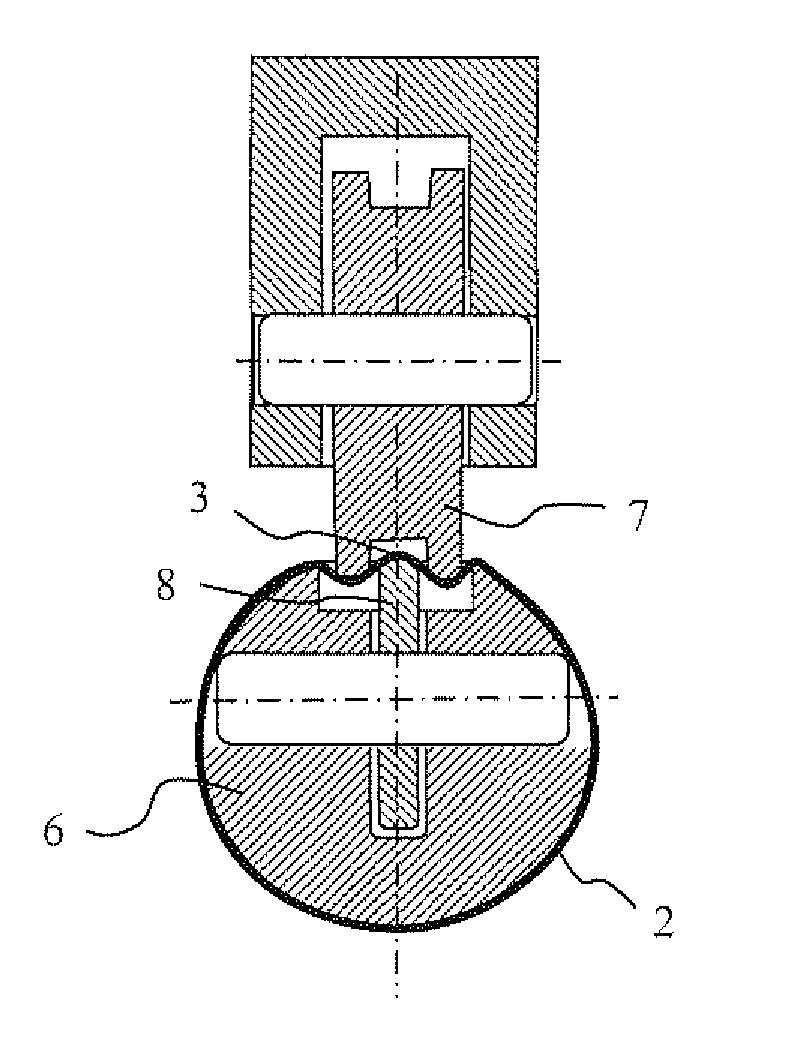
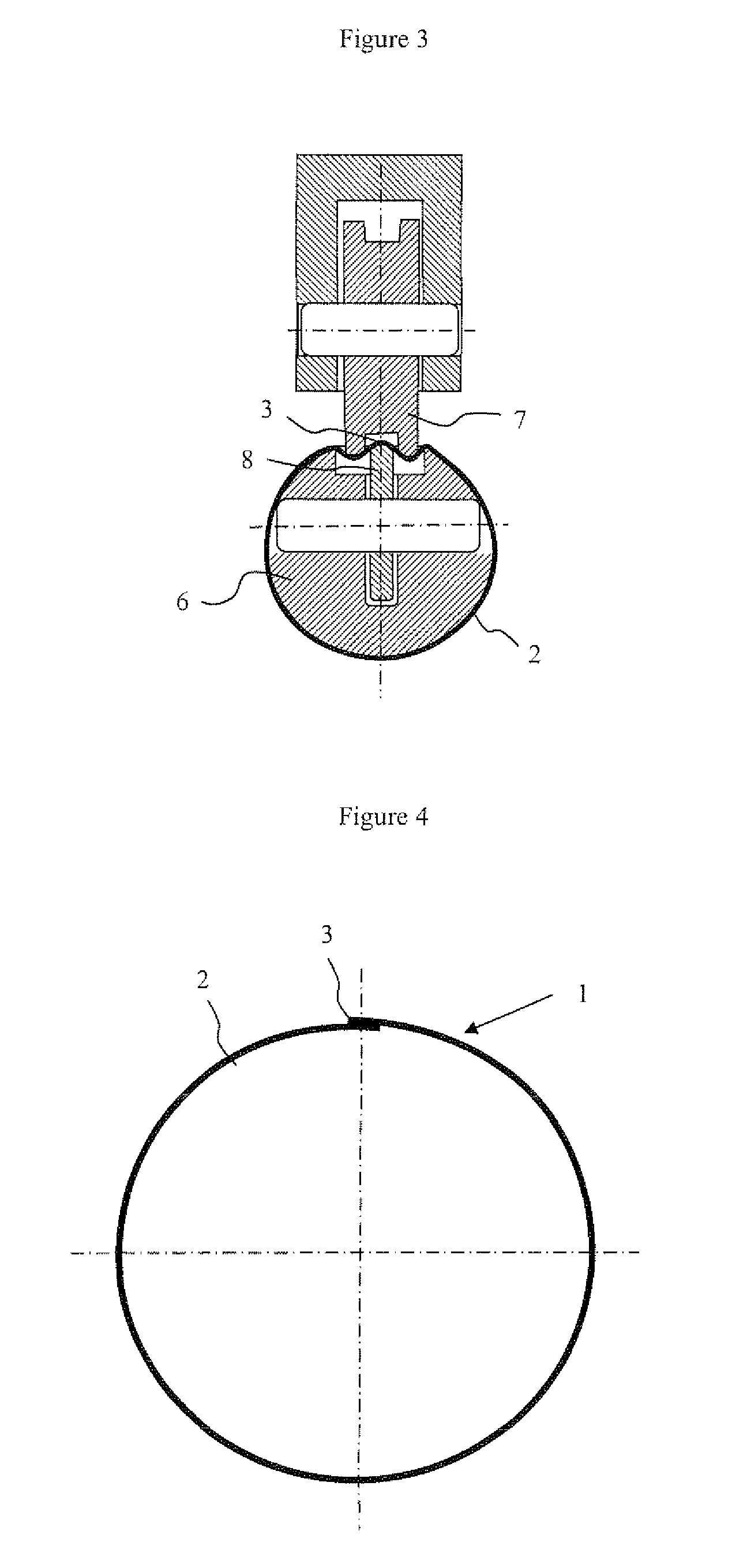
[0039]the invention consists of a welding method that includes an operation of elongating the welded zone in the transverse direction, i.e. in a direction perpendicular to the axis of the tube. An example of a device for elongating the welded zone in the transverse direction is illustrated in FIG. 3. This device, inserted into a welding rod, is illustrated in a cross-sectional view of the welding rod 6, said cross section being perpendicular to the axis of the rod. This device is formed from a set of rollers 7 external to the rod and of rollers 8 housed in the rod which act together to elongate the welded zone 3. Only the welded zone 3 is elongated, the laminate 2 forming the tubular body not being deformed. The elongation of the welded zone 3 is adjusted via the pressure exerted by the rollers 7, said pressure having the effect of transversely elongating the welded zone 3. The number and diameter of the rollers 7 and 8 are adjusted according to the laminate and according to the wel...

third embodiment

[0040]the invention consists in elongating the welded zone 3 longitudinally and transversely. The third embodiment may be implemented by the sequential use of the devices illustrated in FIGS. 3 and 4. A device enabling simultaneous longitudinal and transverse elongation may also be used.

[0041]The first, second and third embodiments of the invention make it possible to compensate for the shrinkage of the welded zone during cooling and to prevent the shrinkage stresses that deform the tubular body. After elongation, the tubular body, the temperature of which is preferably uniform over its entire circumference, is cooled to the ambient temperature uniformly. This results in a tubular body having no out-of-roundness defect. The cross section of this tubular body is illustrated in FIG. 5, in which the out-of-roundness defects close to the welding zone 3 have been eliminated.

[0042]In a manufacturing method in which the laminate is not moving during the welding operation, many devices appl...


PUM

PropertyMeasurementUnit
Temperatureaaaaaaaaaa

Abstract

The invention relates to a method of welding a laminate for the production of flexible tubular plastic bodies, which method comprises the following operations:
    • a laminate is shaped around a welding rod;
    • the ends of the laminate to be welded are heated;
    • said ends are pressed together and at least partly cooled;
    • the welded zone is deformed so as to increase its area; and
    • the welded zone is cooled.
The invention also relates to a device suitable for using the aforementioned method.

Description

FIELD OF THE INVENTION [0001]The invention relates to the manufacture of flexible packaging by the welding of plastic films. More specifically, the invention relates to the production of flexible tubes intended for storing and delivering liquid or pasty products.PRIOR ART [0002]Flexible tubes consisting of a head and a flexible skirt obtained by welding a web called a “laminate”, the laminate being formed from several plastic or metal layers, are known. These skirts are obtained by unwinding a web, by forming the web into a tubular body, by welding the ends of the web together, generally forming a slight overlap, and finally by cutting the tubular body into segments of identical length. A tube head is then welded or moulded onto the end of said skirt. The tube head includes a neck with an orifice and a shoulder that joins the neck to said skirt. The tube is thus delivered to the filler, head down and with the delivery orifice closed off (for example by a screwed cap) so as to be fil...

Claims


Application Information

Patent Timeline
IPC IPC(8): B29C65/02
CPCB29C53/20Y10T156/1038B29C65/02B29C66/0324B29C66/034B29C66/1122B29C66/1142B29C66/344B29C66/4322B29C66/92B29C66/9241B29K2101/12B29L2009/00B29L2009/003B29L2023/001B29L2023/005F16L9/17B29C53/50Y10T156/1013B29C66/93431B29C66/93451B29C66/93441B29C65/00B29C66/934B29C66/0342B29C66/723B29C66/71B29C66/72321B29C66/49B29K2023/06
Inventor THOMASSET, JACQUES
Owner AISAPACK HLDG SA
Why Eureka
Try Eureka