Leaky cable

a leaky coaxial cable and cable technology, applied in the direction of slot antennas, waveguides, antennas, etc., can solve the problems of wasting the electric power designated for the communication partner, aesthetically unfavorable, and installing leaky coaxial cables in places where they are noticeable, so as to inhibit an increase in manufacturing costs, reduce the effect of leakage, and reduce the number of cables

Active Publication Date: 2010-08-05
THE FUJIKURA CABLE WORKS LTD
View PDF5 Cites 20 Cited by
  • Summary
  • Abstract
  • Description
  • Claims
  • Application Information

AI Technical Summary

Benefits of technology

[0015]Patent Document 1 attempting to cope with the problem (1) with Non-patent Document 1 described above, requires a sophisticated technology for extruding sheaths, pushing up the processing costs, and also requires a larger amount of sheath material, pushing up the material costs. As a result, according to Patent Document 1, the manufacturing costs increase. In addition, according to Patent Document 2, the formation of the marker means, the concrete example of which is a line whose color is different from the color of the sheath, requires an additional manufacturing step and a sophisticated manufacturing technology. As a result, the processing costs increase.
[0022]Another exemplary embodiment provides a leaky cable capable of: inhibiting electromagnetic waves from leaking wastefully; thus inhibiting the occurrence of any higher-order mode; and accordingly radiating electromagnetic waves stably.

Problems solved by technology

When such a leaky coaxial cable is installed with the outer conductor including slots being left twisted, the radiation direction changes, wasting the electric power designated for the communication partner.
Moreover, it is likely that a sufficient amount of electric power fails to reach the communication partner, so that the communications is disconnected.
This means that, if the communication partner is only in front of the slots, electromagnetic waves are radiated wastefully.
Installing leaky coaxial cables in places where they are noticeable, such as in buildings, particularly hotels, offices and houses, is aesthetically unfavorable because of their protruding impression which stands out.
Despite its advantage, the technology disclosed in Non-patent Document 1 has various problems as follows.
(1) The slots on the outer conductor need to be positioned exactly behind a supporting line, and complicated mechanisms are required to prevent the cable portion as the main body from being twisted with respect to the supporting line during the manufacturing process.
(3) The manufacturing process requires sophisticated and expensive manufacturing machines such as an extruder for insulators and an extruder for sheaths which are installed only in cable manufactures, and accordingly pushes up the manufacturing costs.
As a result, according to Patent Document 1, the manufacturing costs increase.
As a result, the processing costs increase.
First, a step of forming the insulator and a step of forming the sheath need to be added to the general steps of manufacturing the leaky coaxial cable, and this addition accordingly pushes up the processing costs, Secondly, the material for the insulator, the material for the outer conductor, and the material for the sheath push up the material costs.
As a result, the manufacturing costs increase.
These transmission modes cause part of electromagnetic waves to be leaked outward from the interstice between the outer conductors, and accordingly increase the attenuation of the electromagnetic waves.
This makes the leaky coaxial cable incapable of radiating the electromagnetic waves stably.
This makes it impossible to obtain a stable radiant electric power from the leaky coaxial cable.
Furthermore, in general, the waveguide is made of a metal plate, and is accordingly unpliable.
This makes it difficult to install the leaky coaxial cable.
This requirement makes the leaky coaxial cable using the waveguide expensive.
Nevertheless, being of an antenna type, such a leaky coaxial cable is incapable of radiating electromagnetic waves to a wider space unlike general leaky coaxial cables or waveguides.

Method used


Image

  • Leaky cable
  • Leaky cable
  • Leaky cable

Examples


first embodiment

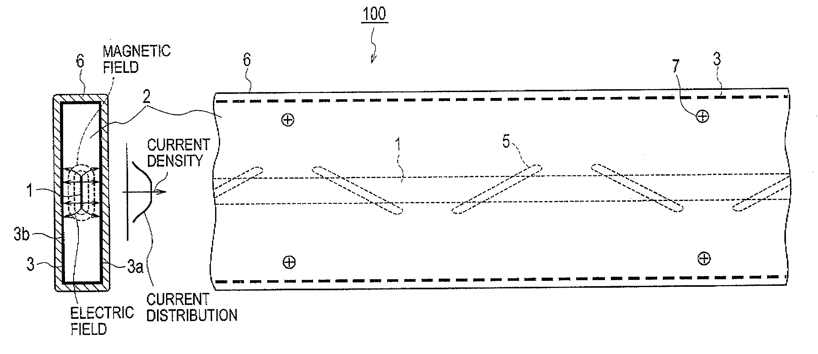
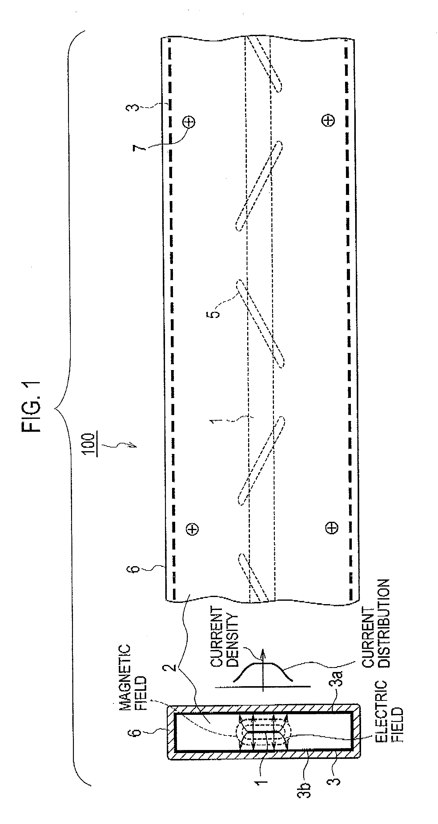
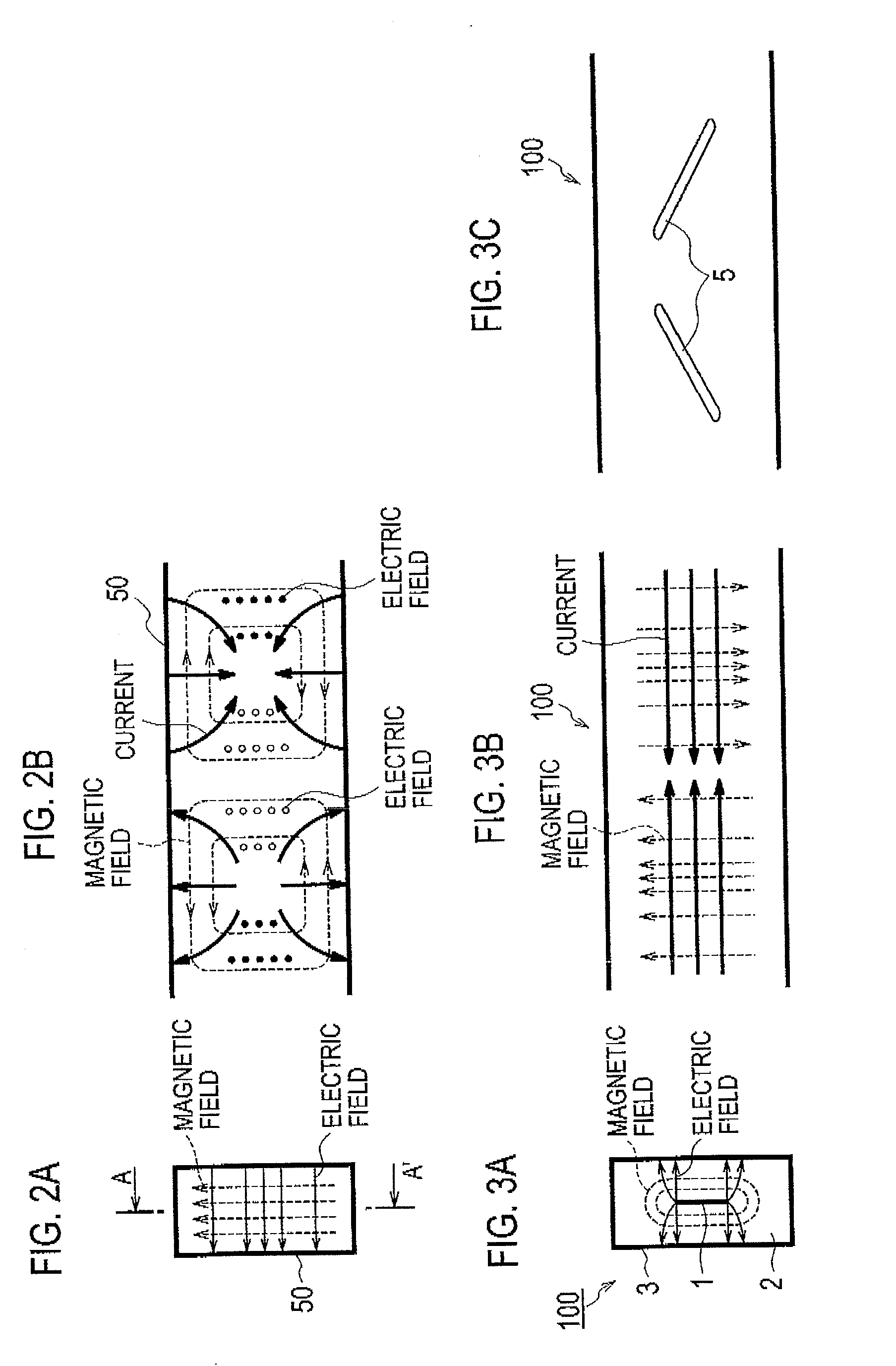
[0043]FIG. 1 is a block diagram of a leaky transmission line (leaky cable) 100 according to a first embodiment of the present invention. The left part of FIG. 1 shows a drawing of a transverse cross section of the leaky transmission line 100 taken perpendicular to the lengthwise direction of the leaky transmission line 100, and shows electric fields and magnetic fields by thin solid lines and dashed lines, respectively. The right part of FIG. 1 shows a drawing of a longitudinal cross section of the leaky transmission line taken parallel to the lengthwise direction of the leaky transmission line 100. The middle part of FIG. 1 shows a distribution of electric current flowing in an outer conductor 3. FIGS. 2A and 2B show distributions of electromagnetic field of a waveguide 50. FIGS. 3A, 3B and 3C show distributions of electromagnetic field of the leaky transmission line 100. FIG. 4 shows a perspective view of the leaky transmission line 100.

[0044]As shown in FIG. 1, the leaky transmis...

second embodiment

[0075]Next, descriptions will be provided for a leaky transmission line (leaky cable) according to a second embodiment of the present invention. FIGS. 9A and 9B show a leaky transmission line 200 according to the second embodiment of the present invention. FIG. 9A shows a drawing of a transverse cross section of the leaky transmission line 200 taken perpendicular to the lengthwise direction of the leaky transmission line 200. FIG. 9B shows a drawing of a longitudinal cross section of the leaky transmission line 200 taken in parallel to the lengthwise direction of the leaky transmission line 200. Note that the leaky transmission line 200 according to this embodiment is configured to radiate electromagnetic waves from only one side on the widthwise axis of the leaky transmission line 200 (namely, to only the right on the drawing).

[0076]As shown in FIGS. 9A and 9B, the leaky transmission line 200 includes: a central conductor 201 having a rectangular cross section; an outer conductor 2...

third embodiment

[0078]Next, descriptions will be provided for a leaky transmission line (leaky cable) according to a third embodiment of the present invention. FIGS. 10A and 10B show a leaky transmission line (leaky cable) 300 according to the third embodiment. The left part of FIG. 10A shows a transverse cross section of the leaky transmission line 300 taken perpendicular to the lengthwise direction of the leaky transmission line 300, and shows electric fields and magnetic fields by thin solid lines and dashed lines, respectively. The right part of FIG. 10A shows a distribution of electric current which flows in an outer conductor 303. FIG. 10B shows a longitudinal cross section of the leaky transmission line 300 taken in parallel to the lengthwise direction of the leaky transmission line 300. This drawing illustrates that the leaky transmission line 300 radiates electromagnetic waves from only one side on the widthwise axis of the leaky transmission line 300 (namely, to only the right in the draw...


PUM


Abstract

A leaky cable with a central conductor, and an outer conductor having a rectangular cross section surrounding the central conductor. The outer conductor has a first and a second surface parallel to each other, and at least one slot row formed in at least one of the first and second surface. The slot row is formed in a first direction of the outer conductor and includes a plurality of slots each configured to form a leaky electromagnetic field. An insulator is disposed between the central conductor and the outer conductor. The width of the rectangular cross section in a direction parallel to the first and second surfaces is less than half of a wavelength of an electric signal transmitted through the leaky cable.

Description

CROSS REFERENCE TO RELATED PATENT APPLICATION[0001]This application claims priority from Japanese Patent Application No. 2009-025197 filed on Feb. 5, 2009, the entire contents of which are incorporated by reference herein.BACKGROUND[0002]1. Technical Field[0003]Exemplary embodiments of the present disclosure relate to a leaky cable, and particularly to a high-quality leaky cable which has a simple configuration requiring no twist preventing mechanism and thereby inhibiting an increase in manufacturing costs, and which has such a flat appearance that gives no protruding impression.[0004]2. Description of the Related Art[0005]In this description, terms leaky transmission line and leaky cable refer to a transmission line configured to produce an electromagnetic field around the transmission line by causing part of energy of an electric signal transmitted in the transmission line, to be propagated in a space outside of the structure of the transmission line. What is typical of this leak...

Claims


Application Information

Patent Timeline
Patent Type & Authority Applications(United States)
IPC IPC(8): H01Q13/22H01P3/00
CPCH04B5/0018H01Q13/203
Inventor SUZUKI, FUMIOTAKANO, KAZUHIKO
Owner THE FUJIKURA CABLE WORKS LTD
Why Eureka
Try Eureka