
Exhaust gas processing system and processing method

a processing system and exhaust gas technology, applied in the direction of emission prevention, separation process, lighting and heating apparatus, etc., can solve the problems of high maintenance costs, easy damage to compressors and other equipment, and easy damage to sulfur oxides, etc., to achieve efficient recovery, high purity, and efficient recovery

Active Publication Date: 2020-01-14
IHI CORP
View PDF39 Cites 0 Cited by
  • Summary
  • Abstract
  • Description
  • Claims
  • Application Information

AI Technical Summary

Benefits of technology

The patent text describes a method for removing sulfur and nitrogen oxides from exhaust gas using a combination of desulfurization and denitration techniques. This method does not require any chemical agents and uses relatively inexpensive limestone as an absorbent. However, the recovered carbon dioxide from the exhaust gas needs to be efficiently purified for economic use. Additionally, the challenge of scattered particles in the exhaust gas during the desulfurization process needs to be addressed to prevent damage to equipment and increase energy consumption. The overall economic efficiency of the exhaust gas processing process is critically dependent on the efficient removal of sulfur and nitrogen oxides and the efficient recovery of carbon dioxide.

Problems solved by technology

However, acids (sulfuric acid and sulfurous acid) generated from the sulfur oxides easily damage the compressor and other equipment.
Accordingly, if this technique is used singly to attain desulfurization and denitration, a large burden is imposed onto the apparatus to cause a problem about costs for maintaining the facilities.
It is also difficult to attain the desulfurization and the denitration with a high removing efficiency.
In the meantime, about denitration methods, a reduction method in which a hydrogen source such as ammonia is used makes difficult the reduction in the processing cost.
Such scattered particles easily cause a failure of wear and breakdown in the subsequent machinery.

Method used


Image

  • Exhaust gas processing system and processing method
  • Exhaust gas processing system and processing method
  • Exhaust gas processing system and processing method

Examples


Embodiment Construction

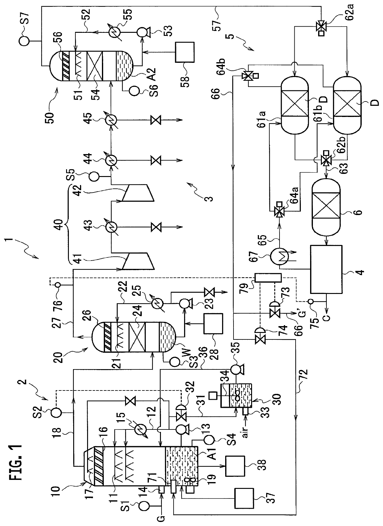
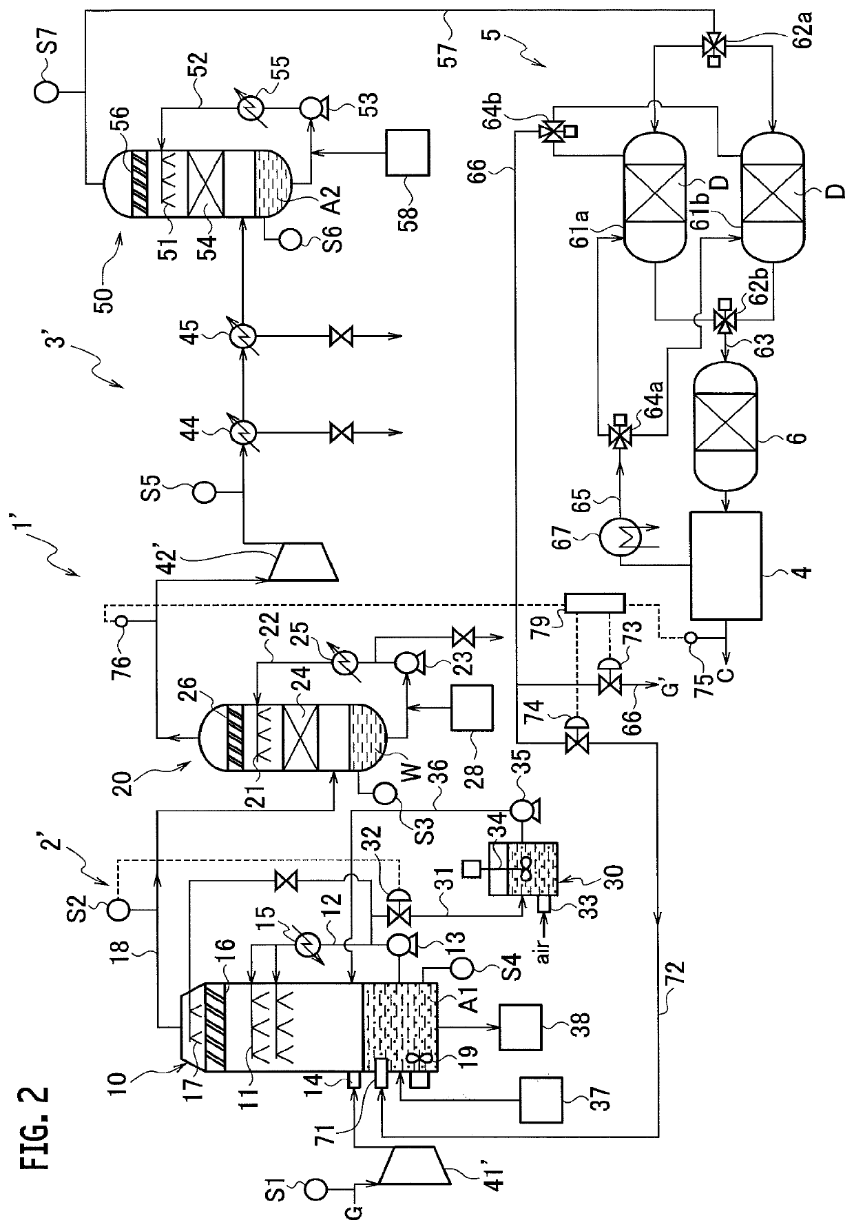
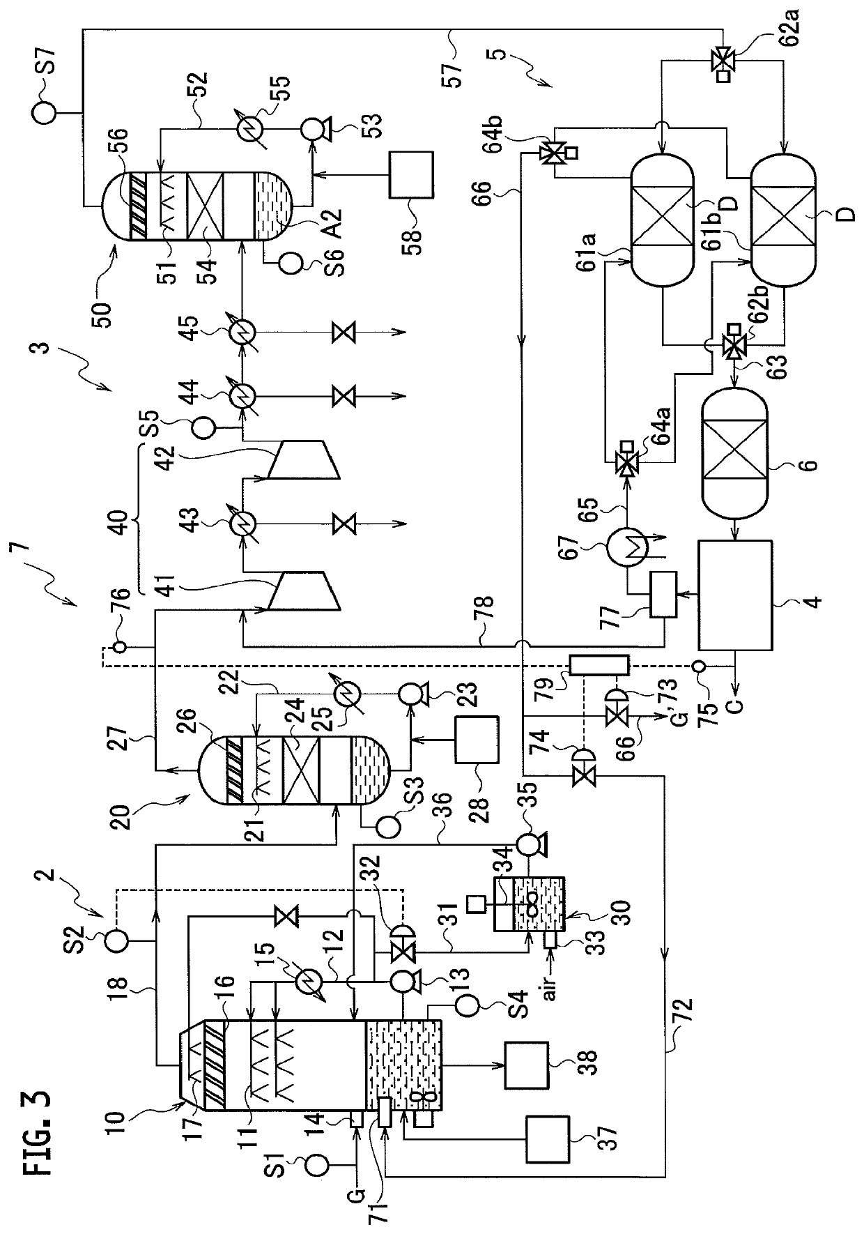
[0030]Main components of combustion gas and the like exhaust gases are water and carbon dioxide, and they further contain, as impurities, sulfur oxides, nitrogen oxides, hydrogen chloride, oxygen, mercury, soot and dust (particulate matters) and the like in a small proportion, and also contain inert argon and nitrogen. The amount of oxygen remaining in exhaust gases is varied in accordance with the combustion conditions, but the oxygen content may be approximated at about 5% and it is similar in the exhaust gases that the above-mentioned impurities are contained in a small proportion. Accordingly, oxygen and the like remain in a small proportion in the exhaust gas after subjected to desulfurization and denitration. Thus, if carbon dioxide in the exhaust gas is refined and recovered with high purity, carbon dioxide containing oxygen, argon and nitrogen in a high concentration is discharged as the purification residue after the recovery. In order to increase the recovery efficiency of...


PUM

PropertyMeasurementUnit
heightaaaaaaaaaa
heightaaaaaaaaaa
temperatureaaaaaaaaaa

Abstract

An exhaust gas processing system having excellent durability and good desulfurization and denitration efficiency is provided to efficiently recover carbon dioxide with high purity and reduced processing costs. The exhaust gas processing system has: a desulfurization unit removing sulfur oxides from the exhaust gas by the limestone-gypsum method; a denitration unit arranged downstream of the desulfurization unit to remove nitrogen oxides from the exhaust gas; a carbon dioxide recovery arranged downstream of the denitration unit to recover carbon dioxide from the exhaust gas; and an oxygen supply unit supplying to the desulfurization unit with a faction of the recovered gas from the carbon dioxide recovery unit as oxygen source. An analyzer is used to monitor the purity and recovery ratio of the carbon dioxide recovered, and the supplied ratio of recovered gas is adjusted, based on the monitored purity and recovery ratio.

Description

CROSS REFERENCE TO RELATED APPLICATIONS[0001]This application is a continuation application of International Application No. PCT / JP2014 / 073815, filed on Sep. 9, 2014, which claims priority of Japanese Patent Application No. 2013-191408, filed on Sep. 17, 2013, the entire contents of which are incorporated by references herein.BACKGROUND[0002]Technical Field[0003]Embodiments described herein relates to an exhaust gas processing system and a processing method for removing a sulfur oxide, a nitrogen oxide and the like from an exhaust gas containing carbon dioxide, such as combustion gas, to separate and recover carbon dioxide.[0004]Description of the Related Art[0005]In thermal power stations, ironworks, boilers and other facilities, fuels such as coal, heavy oil and extra heavy oil are used in a large quantity. Sulfur oxides, nitrogen oxides, and carbon dioxide discharged by the burning of the fuels need quantitative and concentration limitations with respect to the release thereof fr...

Claims


Application Information

Patent Timeline
Patent Type & Authority Patents(United States)
IPC IPC(8): B01D53/50B01D53/64B01D53/62B01D53/34B01D53/26B01D47/06B01D53/56C01B32/50
CPCB01D53/261B01D53/346B01D53/501B01D47/06B01D53/62B01D53/64B01D53/56B01D2257/602B01D53/77B01D53/002B01D53/30B01D53/75B01D53/78F23J15/04B01D2251/102B01D2256/22B01D2258/0283F23J2215/10F23J2215/20F23J2215/50F23J2215/60F23J2219/40C01B32/50Y02E20/32Y02P20/151Y02C20/40
Inventor NAITO, TOSHIYUKI
Owner IHI CORP
Learn More