Eureka AIR delivers breakthrough ideas for toughest innovation challenges, trusted by R&D personnel around the world.

Display apparatus and imaging system

Active Publication Date: 2010-08-05
CANON KK
View PDF6 Cites 0 Cited by
  • Summary
  • Abstract
  • Description
  • Claims
  • Application Information

AI Technical Summary

Benefits of technology

[0007]It is an object of the present invention to provide a display apparatus, in which red, green, blue and white sub-pixels are used, and deterioration of a display device in an icon display region is reduced to lower the occurrence of burn-in, and an imaging system using the display apparatus.

Problems solved by technology

There is a case where a display device using a self-emission phenomenon, such as the electroluminescence device, may deteriorate due to an emission luminance or emission time.

Method used


Image

  • Display apparatus and imaging system
  • Display apparatus and imaging system
  • Display apparatus and imaging system

Examples


Embodiment Construction

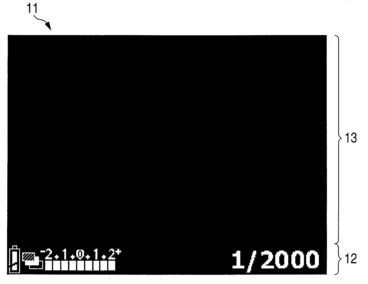
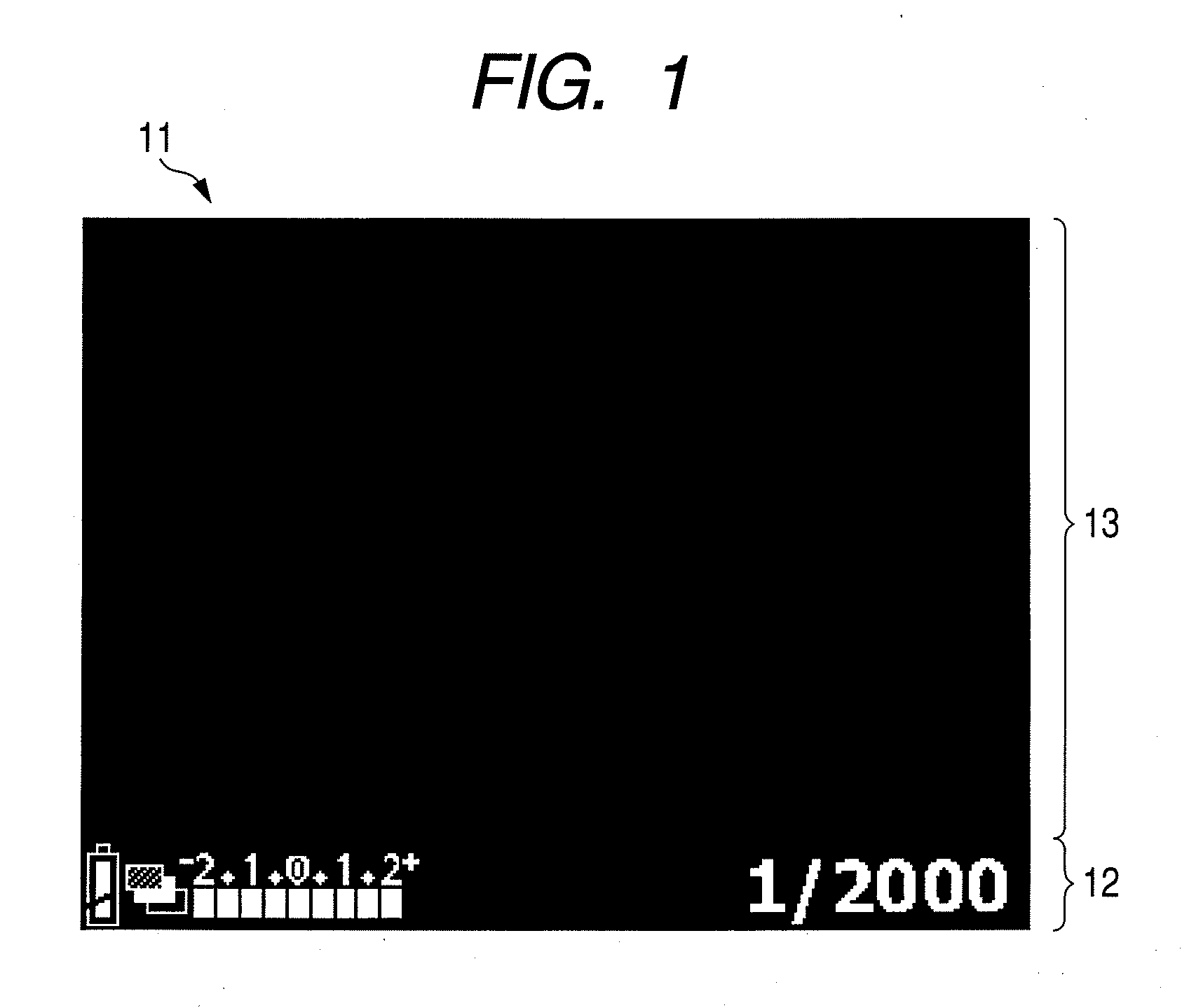
[0019]FIG. 1 illustrates a typical image displayed on a display apparatus used for an imaging system such as a digital camera.

[0020]In the case of the digital camera, an image obtained by photographing or an image signal from a CCD or a CMOS area sensor is displayed on a natural image display region 13. System information including a shutter speed and a remaining battery level is displayed on an icon display region 12. The system information is superimposed on the image (or image signal) to form a display image 11.

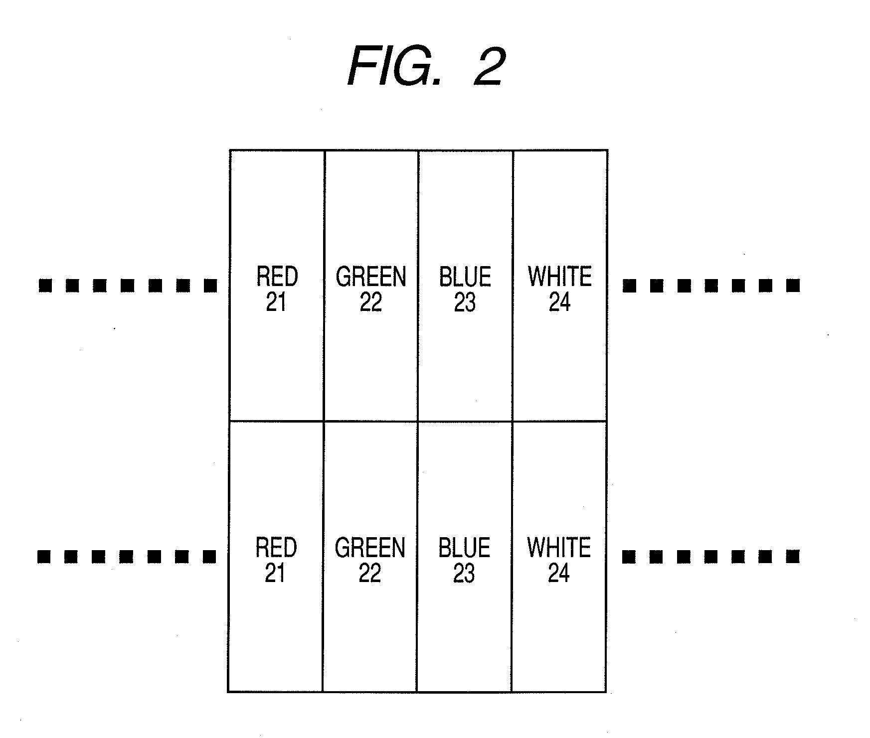
[0021]A shape of the icon display region 12 and a position thereof on the display image 11 are determined at the time of system design. Therefore, the shape and the position are hardly adjusted by a user during the use of the display apparatus. The information is displayed with white color on the icon display region 12 in view of visibility in many cases. In general, when the information is to be displayed with only white color on the icon display region 12 using red, gree...


PUM


Abstract

Provided is a display apparatus, in which a deterioration of a display device in an icon display region is reduced to lower the occurrence of burn-in. The display apparatus includes multiple pixels each including sub-pixels of red, green, blue and white, which are arranged in matrix and a color operation circuit for converting an image signal into a driving signal for the sub-pixels, in which each of the sub pixels includes an electroluminescence device and the color operation circuit adjusts a luminance ratio between the sub-pixels of red, green and blue and the sub-pixel of white based on a display region.

Description

TECHNICAL FIELD[0001]The present invention relates to a small-size full-color display apparatus using a display device by means of electroluminescence, and to an imaging system using the display apparatus, such as a digital camera.BACKGROUND ART[0002]In recent years, as a display apparatus using a display device by means of electroluminescence, in Japanese Patent Application Laid-Open No. 2003-178875, a technique using sub-pixels of four colors of red, green, blue and white is described.[0003]In this technique, a white color display device on which a color filter is stacked is used for display of red, green and blue, and only a white color display device is used for white display. As a result, the color filter is prevented from absorbing light at the time of white display, thereby being capable of suppressing power consumption.[0004]Japanese Patent Application Laid-Open No. 2006-3475 also discloses a technique, in which a luminance ratio between red, green and blue sub-pixels and a ...

Claims


Application Information

Patent Timeline
IPC IPC(8): G09G3/30
CPCG09G3/30G09G2300/0408G09G2340/06G09G2320/046G09G2300/0452
Inventor ISOBE, RYUICHIRO
Owner CANON KK
Why Eureka
Eureka Blog
Learn More