Eureka AIR delivers breakthrough ideas for toughest innovation challenges, trusted by R&D personnel around the world.

Pump with a Sculptured Fluid End Housing

Inactive Publication Date: 2011-06-16
FTS INT SERVICES
View PDF12 Cites 14 Cited by
  • Summary
  • Abstract
  • Description
  • Claims
  • Application Information

AI Technical Summary

Benefits of technology

[0007]The essence of the invention is the discovery that by varying the shape, that is, sculpturing the front side of the fluid end of a high pressure pump, the internal stresses within the fluid housing can be controlled. This allows the pump to be designed in such a manner so as to minimize the mass of the pump end to minimize the possibility of structural failure. For example a frac pump can be designed so that the tendency of the fluid end of the pump to be pumped off the power end is minimized as well as lowering the occurrence of structural failure within the housing due to internal pressure.

Problems solved by technology

Currently the fluid end of the pump tends to be damaged due to pressure imbalances, fatigue, and higher pressures and horsepower.

Method used


Image

  • Pump with a Sculptured Fluid End Housing
  • Pump with a Sculptured Fluid End Housing
  • Pump with a Sculptured Fluid End Housing

Examples


Embodiment Construction

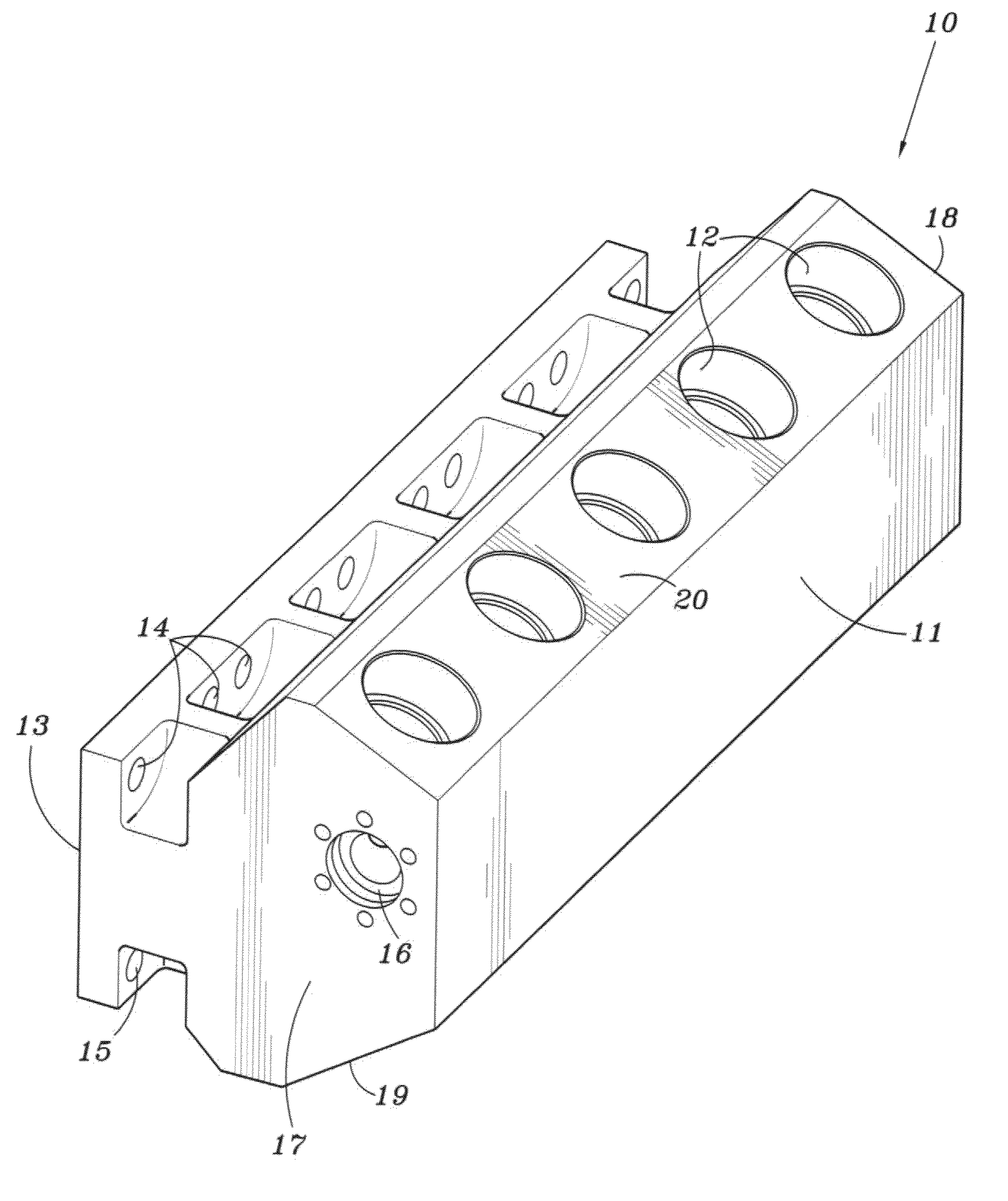
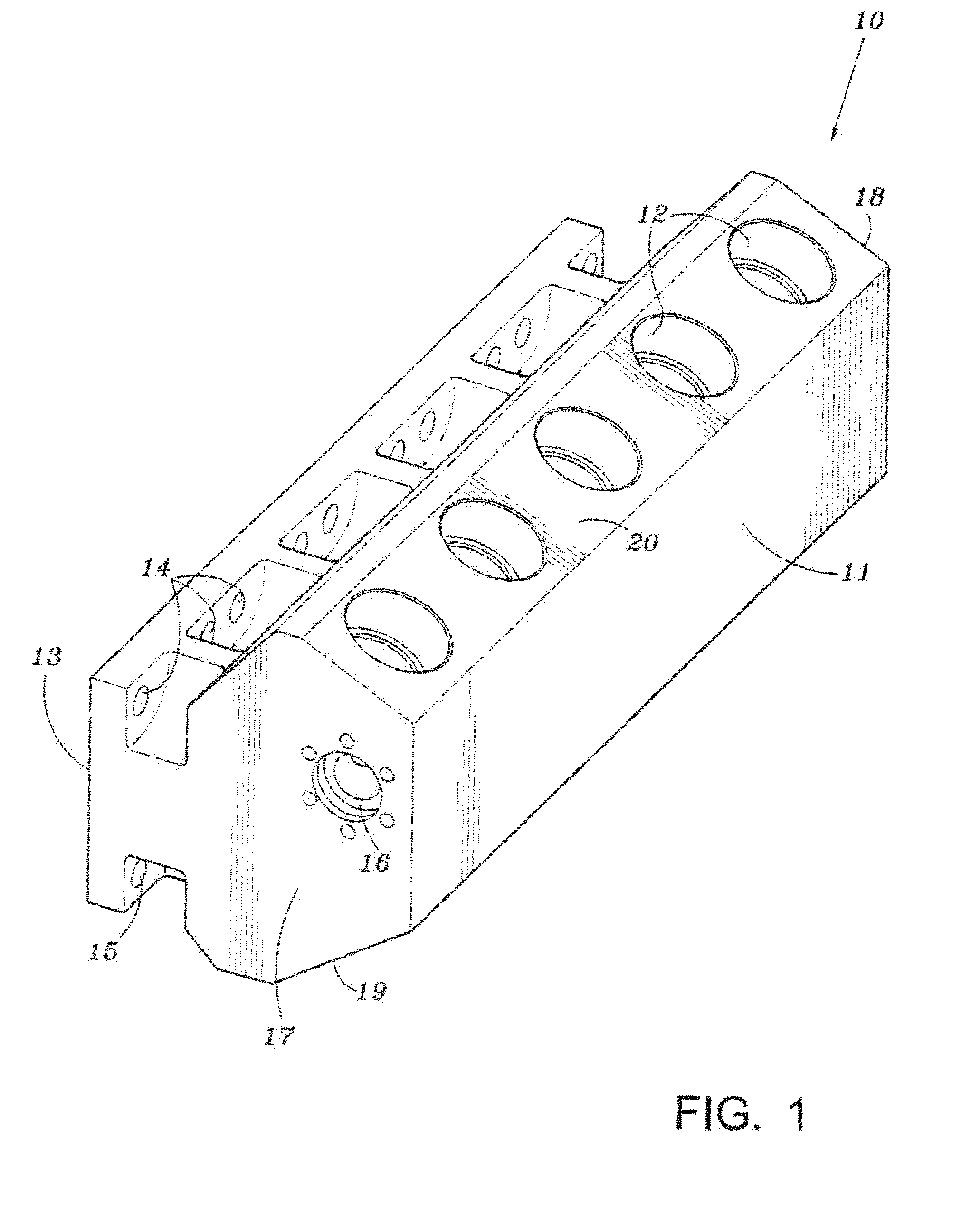
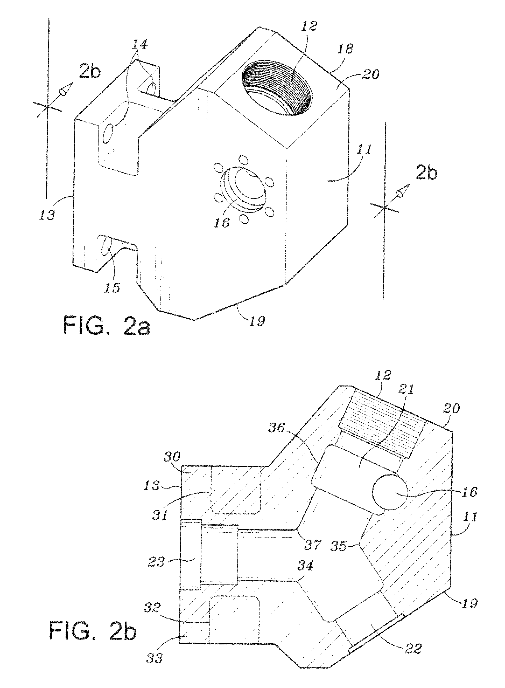
[0026]FIG. 1 illustrates a conventional fluid end 10 of a high pressure pump. The fluid end includes an inclined top surface 20 having a plurality of bores 12 for receiving outlet valve mechanisms which are not shown. Fluid end 10 has a planar front side 11 and a rear side 13 that is adapted to be bolted to the power end 50, shown in FIG. 10. Suitable bores 14, 15 are provided for receiving threaded bolts. A horizontally extending outlet passageway 16 is in fluid communication with each of the outlet chambers 21 of the pumps as shown in FIG. 2B. Fluid end 10 further includes a lower extending inclined portion 19. A plurality of inlet ports 22 are located in portion 19. Planar front side portion 11 externals vertically between inclined surfaces 20 and 19 when the pump is secured to a truck bed. The rear side 13 of the fluid end includes a plurality of bores 23 for receiving the pistons (not shown) which are driven by the power end of the pump. The arrangement of the pistons, the flui...


PUM

PropertyMeasurementUnit
Fractionaaaaaaaaaa
Poweraaaaaaaaaa

Abstract

This invention relates to a method of fabricating or machining the fluid end of a high pressure pump and a fluid end produced by the method. The method includes sculpturing the front side of the fluid end which results in a non-planar surface. In this manner the internal stresses can be varied at critical points within the fluid end.

Description

BACKGROUND OF INVENTION[0001]1. Field of the Invention[0002]This invention relates to the design of fluid pumps used for pumping fluid at a relatively high pressure into a well. One example of such a process is the hydraulic fracturing process for oil and / or gas well applications. These pumps are commonly referred to as frac pumps. Other uses may include pumping cement or other fluids into the well.[0003]In the case of frac pumps, the pumps are typically mounted on a truck / trailer and several may be used in series or in parallel to pump the fracturing fluid under high pressure into the well. As fracturing techniques become more popular and productive there is a continuing need to increase the horsepower capability of the pumps and the flow rate. However, as horsepower and operating pressures increase, so does the size of the pump and the failure rate.[0004]The present invention addresses techniques to balance and / or modify stress loads within the pump housing which permits larger ca...

Claims


Application Information

Patent Timeline
IPC IPC(8): F04B41/06B23P15/00
CPCF04B39/125F04B53/007Y10T29/49236F04B53/162F04B53/16
Inventor SMALL, TONY M.
Owner FTS INT SERVICES
Why Eureka
Eureka Blog
Learn More