Driving method for vacuum fluorescent display, and vacuum fluorescent display
a technology of vacuum fluorescent display and driving method, which is applied in the direction of electric digital data processing, instruments, computing, etc., can solve the problems of reducing display quality, disadvantageous dynamic driving using phosphors with low response speed, and short service life of phosphors that have been developed for low-energy electron excitation, etc., to achieve the effect of enhancing luminous efficiency and luminance li
Active Publication Date: 2010-08-05
NORITAKE ITRONM
View PDF5 Cites 4 Cited by
- Summary
- Abstract
- Description
- Claims
- Application Information
AI Technical Summary
Benefits of technology
[0013]The present invention was developed in order to overcome such problems as those described above, and an object of the present invention is to provide a driving method capable of enhancing the luminous efficiency and luminance life of a vacuum fluorescen
Problems solved by technology
However, except for green-luminescent ZnO:Zn, phosphors that have been developed for low-energy electron excitation generally have a short service life.
Dynamic driving using a phosphor with a low response speed is therefore considered to be disadvantageous for ob
Method used
View moreImage
Smart ImageViewing Examples
Examples
 PUM
 Abstract
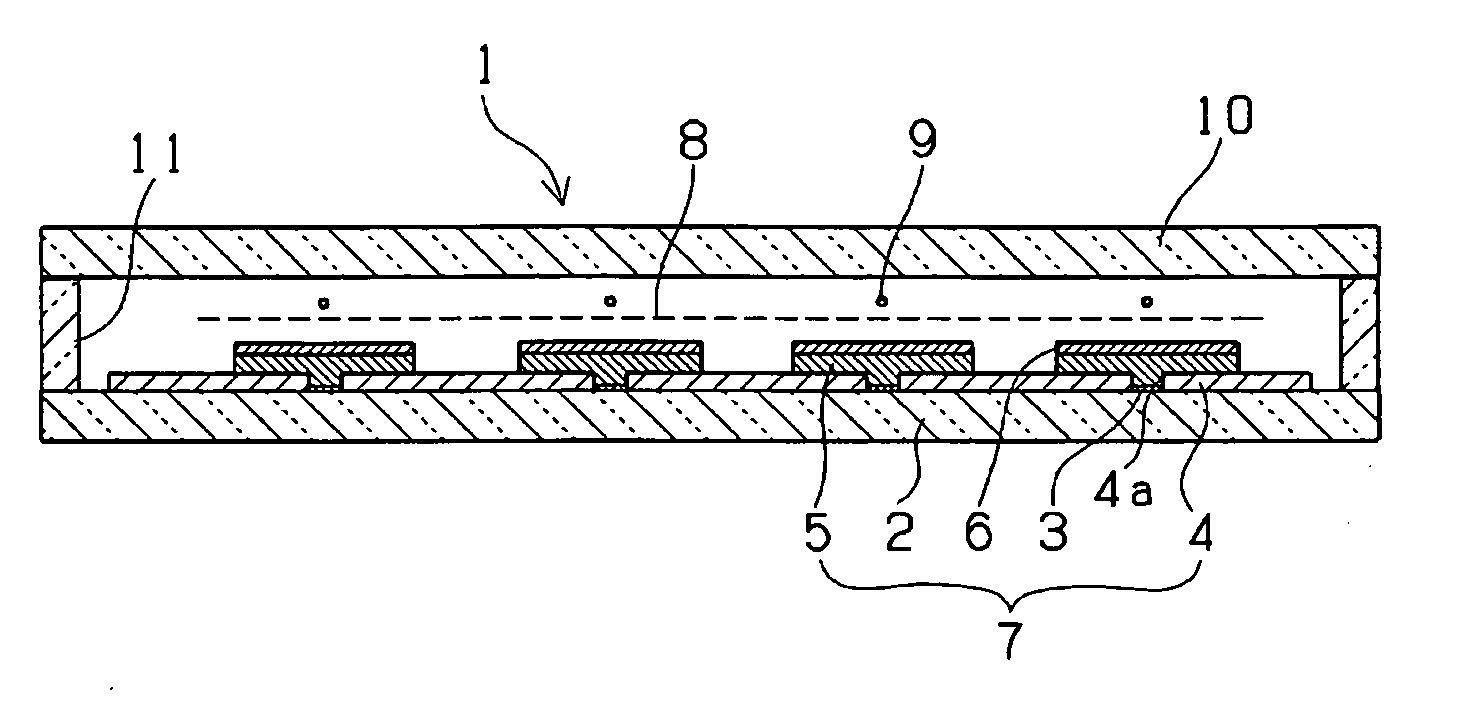
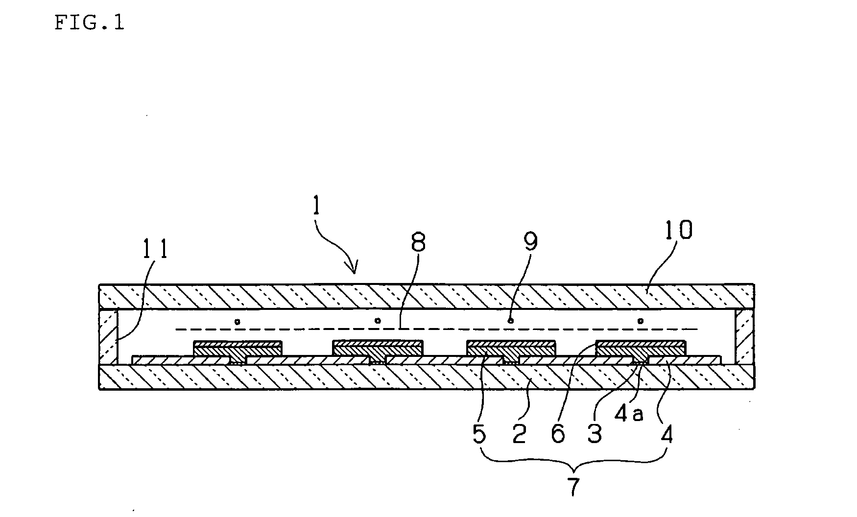
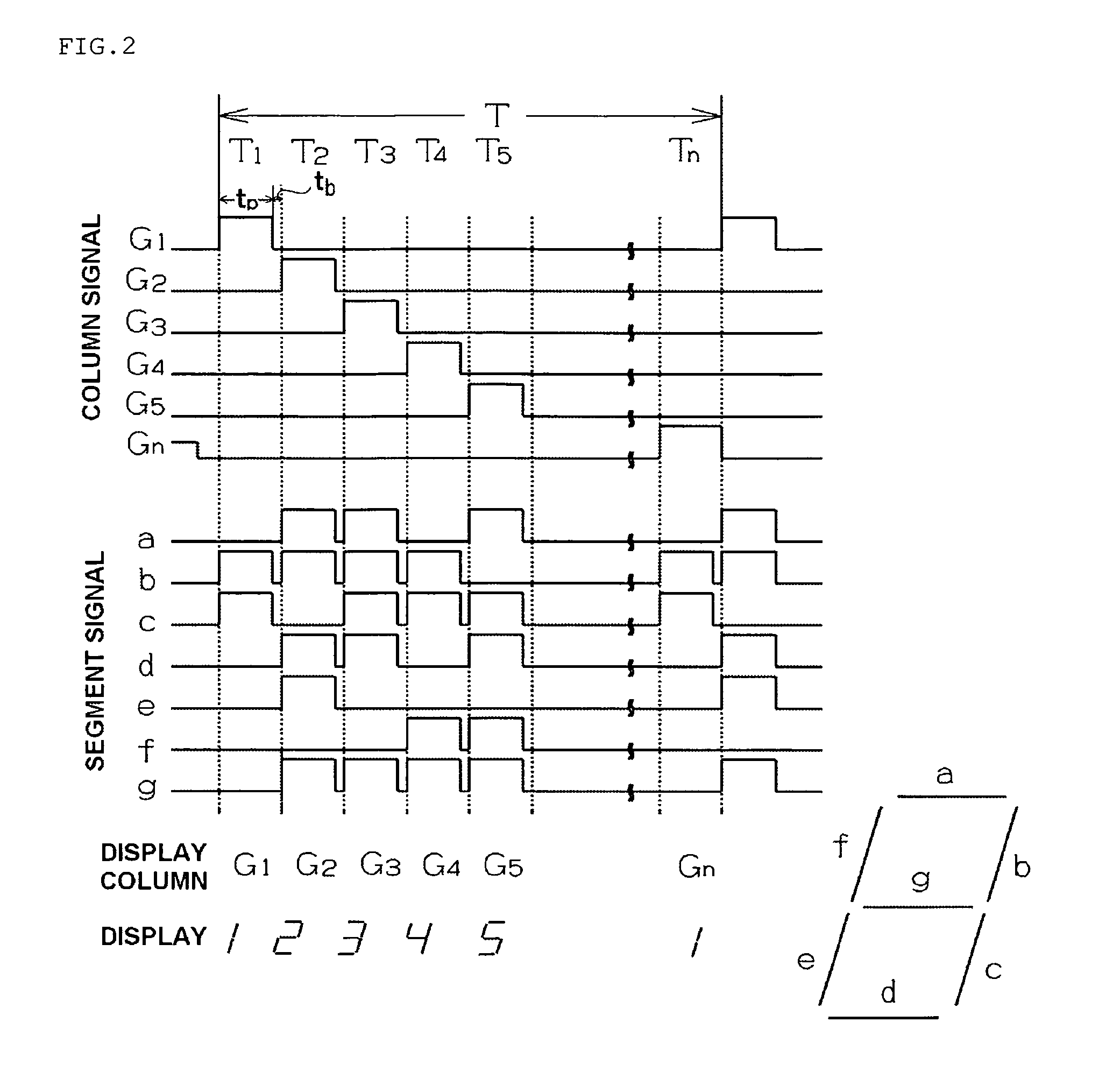
Luminance life can be enhanced in a vacuum fluorescent display that is driven according to a dynamic drive scheme and that uses a phosphor having remarkable luminance saturation. A drive method for a vacuum fluorescent display, having causing a phosphor layer formed on an anode to display under low-energy electron excitation by the dynamic driving, wherein the phosphor included in the phosphor layer is a phosphor in which the luminance increases when a pulse width is reduced under conditions in which the Du is kept the same in the dynamic driving, and in which, after a voltage is applied to the anode and the luminance of the phosphor is saturated, the time at which the luminance value decreases to 10% of the saturation luminance value following stoppage of the voltage application is 200 μsec or more; and wherein the pulse width and pulse repetition period in the dynamic driving are made variable in the direction of maintaining the initial luminance of the phosphor as driving time elapses.
Description
BACKGROUND OF THE INVENTION[0001]1. Field of the Invention[0002]The present invention relates to a driving method for a vacuum fluorescent display, and to a vacuum fluorescent display in which the driving method is used.[0003]2. Description of the Related Art[0004]Besides ZnO:Zn (green), which has excellent luminescence characteristics, numerous types of phosphors in which In2O3 or another electrically conductive substance is added to SrTiO3:Pr (red), CaTiO3:Pr (red), Gd2O2S:Eu (red), Y2O2S:Eu (red), La2O2S:Eu (red), SnO2:Eu (orange), ZnS:Mn (orange), ZnGa2O4 (blue), ZnGa2O4:Mn (green), or the like have been researched and developed as phosphors for low-energy electron excitation in vacuum fluorescent displays and the like.[0005]However, except for green-luminescent ZnO:Zn, phosphors that have been developed for low-energy electron excitation generally have a short service life.[0006]The dynamic drive method is known as a method for driving a vacuum fluorescent display. In the dynam...
Claims
Login to View More Application Information
Patent Timeline
 IPC IPC(8): G09G5/10
CPCG09G3/04G09G2320/043G09G2310/06
Inventor KIKUTA, SHIGEKINAKANISHIMURATA, NOBORUISAKA, MOTOHISA
Owner NORITAKE ITRONM
Features
- R&D
- Intellectual Property
- Life Sciences
- Materials
- Tech Scout
- Unparalleled Data Quality
- Higher Quality Content
- 60% Fewer Hallucinations
Learn More Browse by: Latest US Patents, China's latest patents, Technical Efficacy Thesaurus, Application Domain, Technology Topic, Popular Technical Reports.
© 2025 PatSnap. All rights reserved.Legal|Privacy policy|Modern Slavery Act Transparency Statement|Sitemap|About US| Contact US: help@patsnap.com


