LED driving apparatus and method of controlling luminous power

a technology of led driving and luminous power, which is applied in the direction of instruments, static indicating devices, optics, etc., can solve the problems of increased power consumption, low luminous efficiency of led driving, and low luminous efficiency, so as to minimize power consumption, the effect of luminous efficiency and highest luminous efficiency

Active Publication Date: 2006-04-20
SAMSUNG ELECTRONICS CO LTD
View PDF4 Cites 52 Cited by
  • Summary
  • Abstract
  • Description
  • Claims
  • Application Information

AI Technical Summary

Benefits of technology

[0028] In addition, if the target value is equal to or larger than the predetermined value, switching to the current value control can obtain desired luminous power with as little power as possible. If the PWM control is implemented even when the target value is equal to or larger than the predetermined value, the driving current level inevitably needs to be larger compared with the case of implementing the current value control. The larger current level results in the driving of an LED with a lower luminous efficiency as is apparent from the characteristic diagram of FIG. 9. Therefore, switching to the current value control allows an LED to be driven most efficiently.
[0029] As described above, according to an embodiment of the present invention, luminous power control is switched between the PWM control and the current value control depending on a target value of luminous power. Thus, an LED can be driven with the highest luminous efficiency possible.
[0030] In addition, this control method switching can minimize the power consumed to drive an LED, and further can minimize the heating value of an LED, a driving circuit thereof, and a power supply unit. Thus, the device can be miniaturized.

Problems solved by technology

Since the luminous efficiency of an LED varies depending on the driving current value, the following problems arise in an LED driving apparatus that controls the luminous efficiency of an LED with any of the above-described methods: current value control and PWM control.
However, the target value does not necessarily correspond with the value, and therefore there is a possibility that the LED is driven with a low luminous efficiency.
Accordingly, there is a possibility that the LED is driven with a low luminous efficiency also in the PWM control.
Driving an LED with a low luminous efficiency requires unnecessary extra power higher than originally needed input power, which leads to the increase of power consumption.
In addition, if an LED is driven with a low luminous efficiency, the heating value of the LED, a driving circuit thereof, and a power supply unit is apt to increase, which causes a problem that measures against the heating preclude the miniaturization of the device, for example.

Method used


Image

  • LED driving apparatus and method of controlling luminous power
  • LED driving apparatus and method of controlling luminous power
  • LED driving apparatus and method of controlling luminous power

Examples


first embodiment

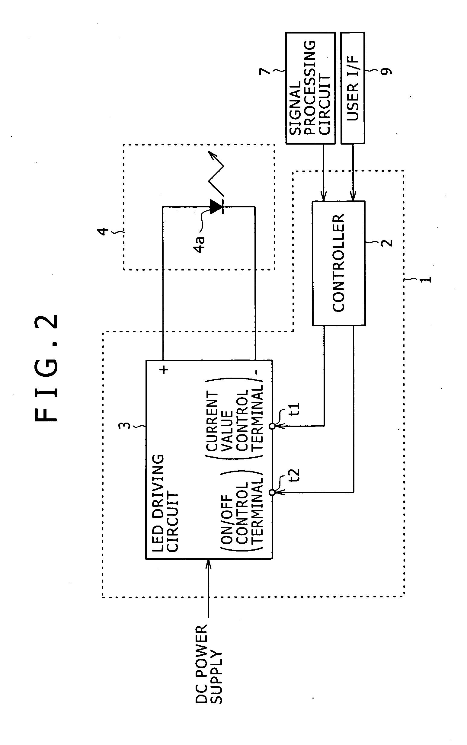
[0056] Note that the controller 2 and the LED driving circuit 3 constitute the LED driving apparatus 1 as the first embodiment as shown also in FIG. 2.

[0057] The controller 2 sets the target value of the luminous power of the LED 4a according to APL information calculated based on a luminance signal from the signal processing circuit 7 shown also in FIG. 1, and according to an instruction input value if an instruction as to the brightness adjustment is input from the user I / F 9. The controller 2 then supplies a control signal to the current value control terminal t1 or the ON / OFF control terminal t2 of the LED driving circuit 3 so that the luminous power of the target value is obtained.

[0058] The controller 2 of the embodiment stores in advance information of the forward current value (driving current level) providing the highest luminous efficiency and the luminous power value (predetermined value) obtained from the forward current value as to the LED 4a.

[0059] The controller 2 s...

second embodiment

[0087]FIG. 5 illustrates the configuration of an LED driving apparatus 20 as the invention.

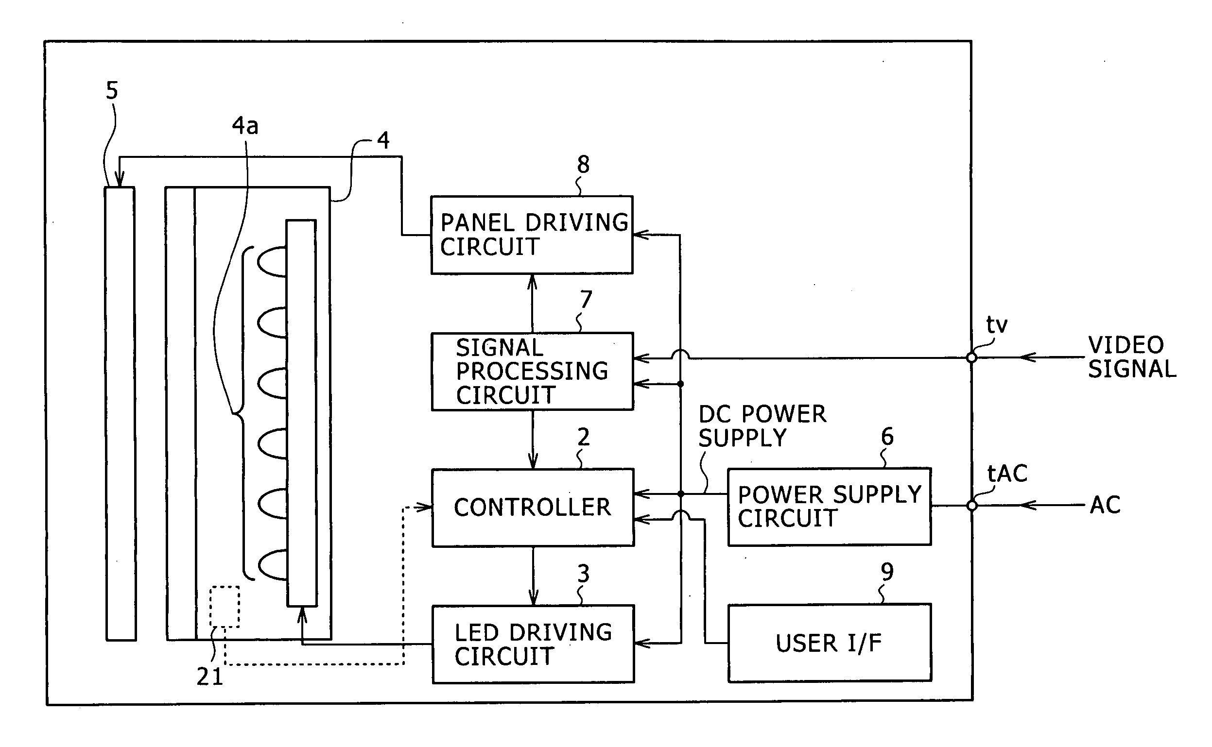
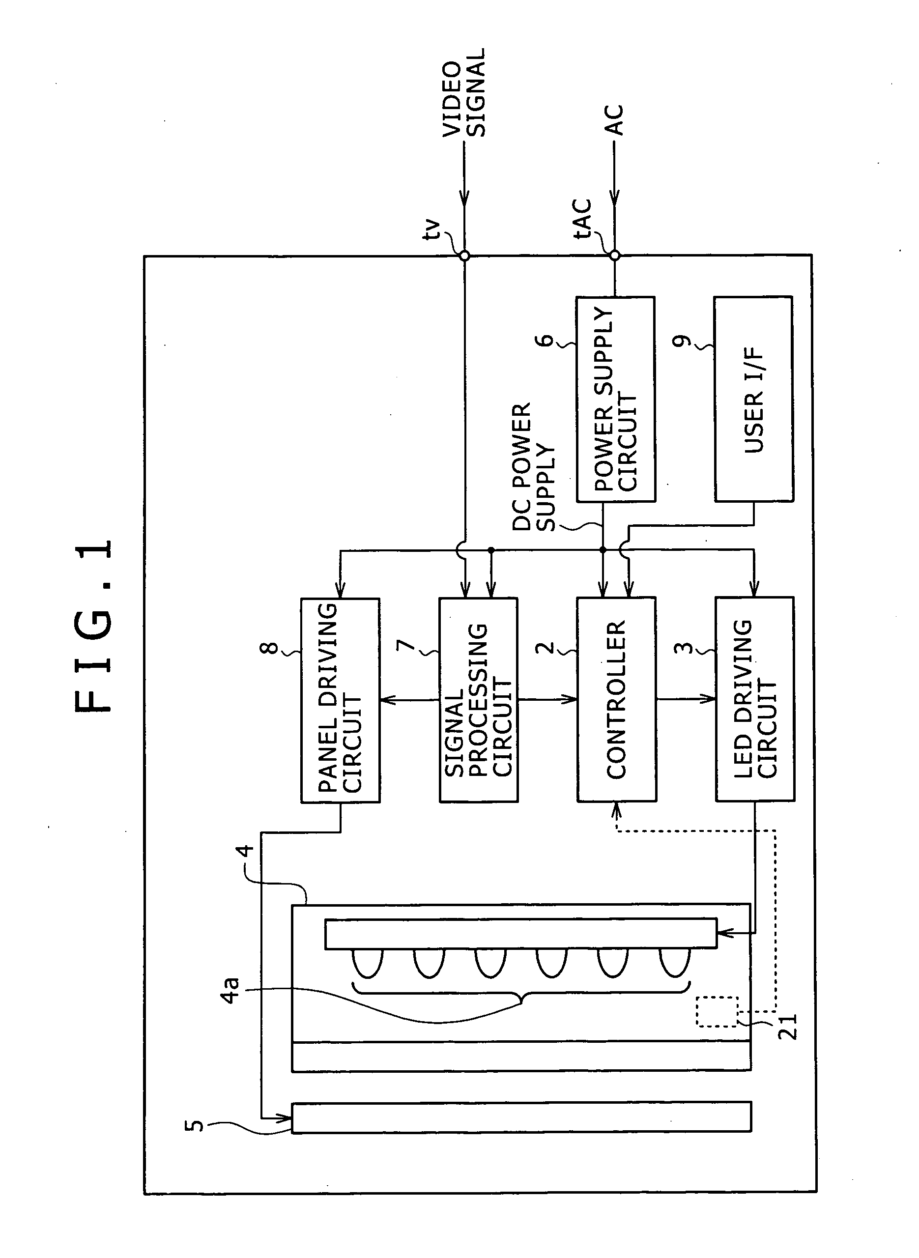
[0088] The LED driving apparatus 20 of the second embodiment also implements switching of the luminous power control methods, implemented in the first embodiment. Furthermore, the LED driving apparatus 20 includes a luminous power sensor 21 in addition to the configuration of the LED driving apparatus 1 shown in FIG. 2. The luminous power sensor 21 is provided at a certain place in the backlight 4 so as to detect the luminous power of the LED 4a (the luminous power sensor 21 is represented with a dashed line in FIG. 1).

[0089] Information of the luminous power detected by the luminous power sensor 21 is input to the controller 2.

[0090] The controller 2 controls the luminous power of the LED 4a based on the luminous power value detected and input by the luminous power sensor 21 as well as based on the target value of luminous power set according to a brightness signal from the signal processin...


PUM


Abstract

A light emitting diode (LED) driving apparatus includes a drive section for driving an LED to emit light, and a control section that controls a driving current supplied from the drive section to the LED. The control section implements luminous power control by controlling an ON/OFF ratio of the driving current if a target value of luminous power of the LED is smaller than a predetermined value. The control section implements luminous power control by controlling a level of the driving current if the target value is equal to or larger than the predetermined value.

Description

CROSS-REFERENCE TO RELATED APPLICATIONS [0001] The present application claims priority from Japanese Patent Application Nos. JP 2004-296148 filed on Oct. 8, 2004 and JP 2005-227965 filed on Aug. 5, 2005, the disclosures of which are hereby incorporated by reference herein. BACKGROUND OF THE INVENTION [0002] The present invention relates to an LED driving apparatus and a method of controlling luminous power. [0003] A display, such as a liquid crystal display, that is not a self-emitting display is provided with a backlight. As such a backlight, one employing cold-cathode tubes as its light source has been known for example. In addition, in recent years, backlights employing light emitting diodes (LEDs), which consume less power, have also been known. [0004] As a method of controlling the luminous power of such a backlight including LEDs, two kinds of methods have been known. One is a current value control method for controlling the level of a driving current supplied to the LEDs. Ano...

Claims


Application Information

Patent Timeline
Patent Type & Authority Applications(United States)
IPC IPC(8): G09G3/36H01L33/00
CPCG09G3/3406G09G2320/0606G09G2320/0633G09G2320/064H05B33/0815H05B33/0851G09G2360/16H05B45/12H05B45/375G02F1/133G02F1/1335
Inventor OYAMA, YOSHIKI
Owner SAMSUNG ELECTRONICS CO LTD
Why Eureka
Try Eureka