Wavelength conversion member and method for manufacturing the same, and light-emitting device, illuminating device, and headlight

a technology of wavelength conversion and wavelength, which is applied in the direction of non-metal conductors, fixed installations, lighting and heating apparatus, etc., can solve the problems of low thermal conductivity of light-emitting sections, inability to directly apply the constitution described in patent literature 1, and inability to achieve direct application of wavelength conversion techniques. , to achieve the effect of reducing the luminous efficiency of wavelength conversion members, and increasing luminous efficiency

Inactive Publication Date: 2014-01-02
SHARP KK
View PDF11 Cites 57 Cited by
  • Summary
  • Abstract
  • Description
  • Claims
  • Application Information

AI Technical Summary

Benefits of technology

[0070]In general, blue-light-emitting fluorescent materials have low luminous efficiency. Thus, a wavelength conversion member that contains a blue-light-emitting fluorescent material dispersed in a glass base material as in the related art must contain a large amount of blue-light-emitting fluorescent material so as to increase luminous efficiency. This reduces the luminous efficiency of the wavelength conversion member. Use of a large amount of blue-light-emitting fluorescent material in the related art also causes a problem of high manufacturing costs of a wavelength conversion member.
[0071]In this respect, a wavelength conversion member according to the present invention contains a fluorescent glass for emitting blue fluorescence in response to excitation light as a sealant. This obviates the necessity of using a blue-light-emitting fluorescent material having low luminous efficiency dispersed in large quantity in a glass base material in a wavelength conversion member according to the present invention. Thus, a wavelength conversion member according to the present invention can have higher luminous efficiency than before and can be manufactured at reduced costs.
[0072]A wavelength conversion member according to the present invention contains a dispersed fluorescent material for emitting fluorescence having a longer wavelength than the blue fluorescence in response to the excitation light. Thus, a wavelength conversion member according to the present invention can emit illumination light having good color rendering properties as a result of the color mixing of blue light emitted from a fluorescent glass and fluorescence emitted from the fluorescent material and having a longer wavelength than the blue fluorescence. For example, a light-emitting device including a wavelength conversion member according to the present invention described below has a wider spectrum in a blue light region and better color rendering properties in the blue region than generally used light-emitting devices that include a blue LED as an excitation light source. Thus, the light-emitting device can have both improved color rendering properties due to the addition of fluorescence having a longer wavelength than blue and improved color rendering properties in the blue region itself.
[0073]Since no blue-light-emitting fluorescent material is used, unlike existing wavelength conversion members that contain a blue-light-emitting fluorescent material, excitation of the fluorescent material or light extraction efficiency from the fluorescent material is not reduced. Thus, a wavelength conversion member according to the present invention achieves high luminous efficiency.
[0074]Thus, a wavelength conversion member according to the present invention can efficiently emit illumination light having good color rendering properties in response to excitation light irradiation.

Problems solved by technology

The existing techniques described above, however, have the following problems.
Thus, there is a problem that the constitution described in Patent Literature 1 cannot be directly applied to the light-emitting device described above.
As a result of extensive studies, the present inventor found that the existing techniques have a problem that a light-emitting section having low thermal conductivity even in contact with a heat-conductive member having high thermal conductivity has insignificant heat sink effects.

Method used


Image

  • Wavelength conversion member and method for manufacturing the same, and light-emitting device, illuminating device, and headlight
  • Wavelength conversion member and method for manufacturing the same, and light-emitting device, illuminating device, and headlight
  • Wavelength conversion member and method for manufacturing the same, and light-emitting device, illuminating device, and headlight

Examples


first embodiment

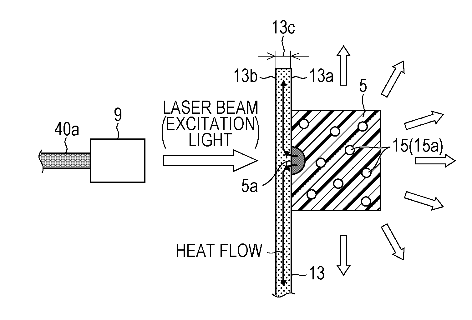
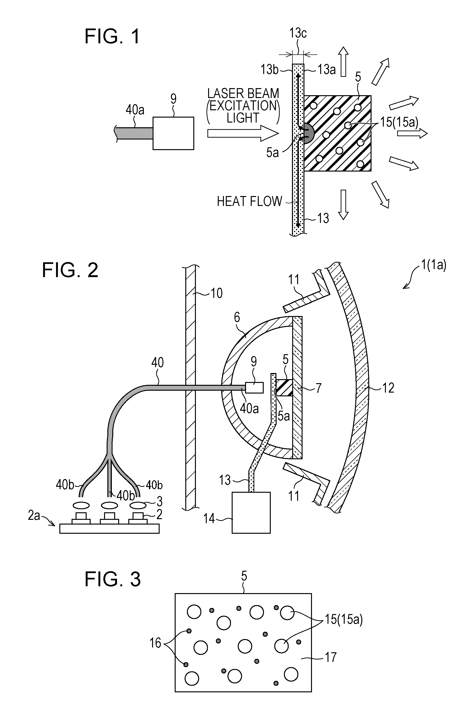
[0109]An automobile headlamp (light-emitting device, illuminating device, headlight) 1 will be described below as an embodiment of an illuminating device according to the present invention. An illuminating device according to the present invention may be a headlamp for vehicles and moving objects other than automobiles (for example, humans, ships, aircrafts, submarines, and rockets) or another illuminating device. Examples of other illuminating devices include searchlights, projectors, household lighting fixtures, interior lighting fixtures, and exterior lighting fixtures.

[0110]The headlamp 1 may satisfy the light distribution characteristic standard of a main-beam headlight (high beam) or the light distribution characteristic standard of a dipped-beam headlight (low beam).

[0111]The headlamp 1 is a headlamp that functions as a high-intensity light source and ensures eye safety.

(Structure of Headlamp 1)

[0112]The structure of the headlamp 1 will be described below with reference to FI...

first example

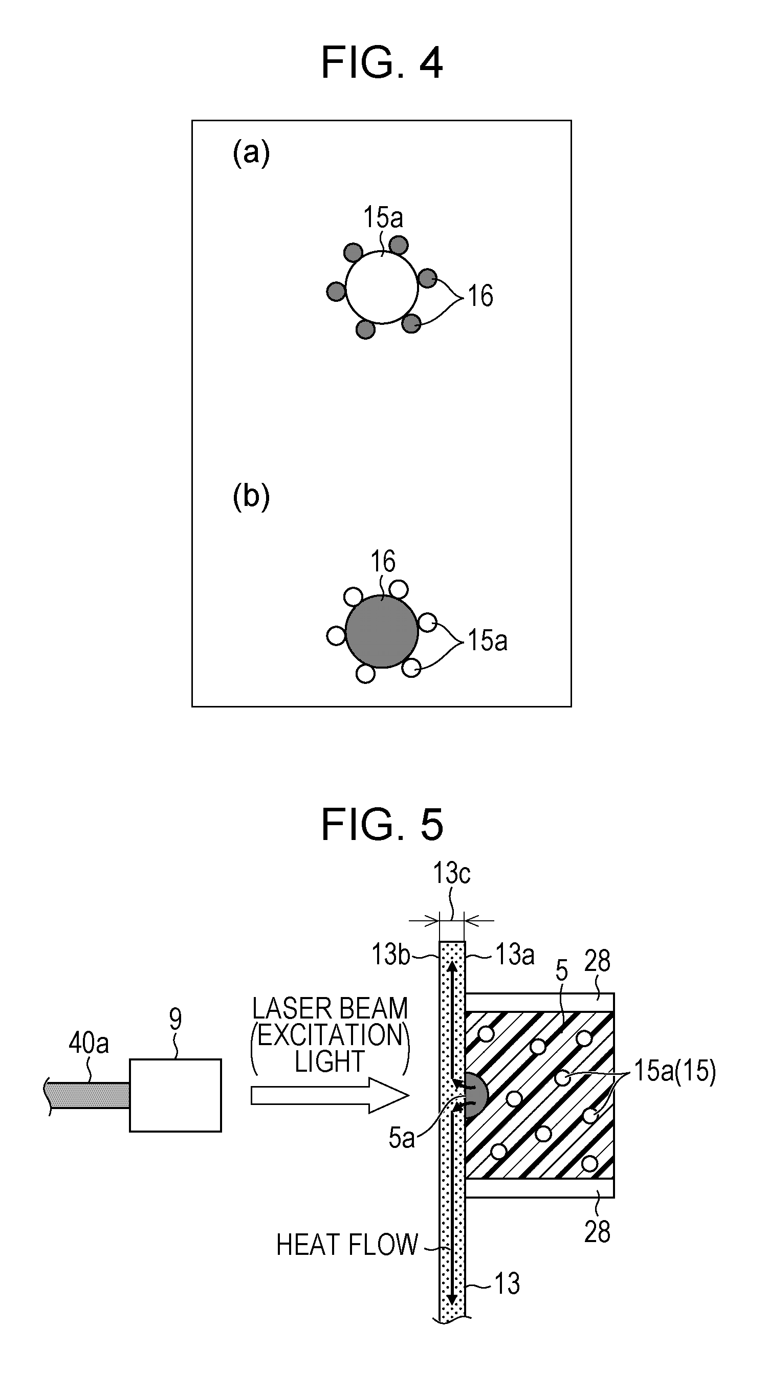
[0202]In a first example described below, synthetic diamond particles are used as the diffusing particles 15, and a green-light-emitting fluorescent material (Caα-SiAlON:Ce3+) and a red-light-emitting fluorescent material (CASN:Eu2+) are used as fluorescent materials. An excitation light source used in combination with the light-emitting section 5 containing these fluorescent materials is a laser diode that emits light at 405 nm.

[0203]First, a glass powder and a fluorescent material powder are weighed at a predetermined ratio and are uniformly mixed (a mixing step). For example, a glass powder and the green-light-emitting fluorescent material (Caα-SiAlON:Ce3+) and the red-light-emitting fluorescent material (CASN:Eu2+) are mixed at a weight ratio of glass powder:green-light-emitting fluorescent material:red-light-emitting fluorescent material=100:6:2. Synthetic diamond particles (having a particle size of 1 μm) are then added to the mixture. The synthetic diamond particles constitut...

second example

[0208]The fluorescent material to be dispersed in the light-emitting section 5 that contains an inorganic glass as a sealant may be a yellow-light-emitting fluorescent material exemplified by a YAG fluorescent material. The weight ratio of the inorganic glass to the fluorescent material is 10:1. Zirconium oxide is then added to the mixture of the inorganic glass powder and the fluorescent material powder. Zirconium oxide constitutes 3% by weight of the mixture. The mixture is then sintered to form a light-emitting section.

[0209]When a YAG fluorescent material is used, a sealant having a particularly low melting point of (500° or less) among low-melting glasses is preferably used. For example, low-melting glasses containing lead oxide or phosphate glasses have particularly low melting points among low-melting glasses and are suitable for the sealant for the YAG fluorescent material.

[0210]An excitation light source used for the YAG fluorescent material is preferably a blue laser diode...


PUM


Abstract

A headlamp (1) includes a laser diode (2) for emitting a laser beam and a light-emitting section (5), which contains a fluorescent substance for emitting fluorescence upon receiving the laser beam emitted from the laser diode (2) and diffusing particles (15) for diffusing the laser beam.

Description

REFERENCE TO RELATED APPLICATIONS[0001]This application is a national stage application under 35 USC 371 of International Application No. PCT / JP2012 / 055928, filed Mar. 8, 2012, which claims the priority of Japanese Patent Application Nos. 2011-058471, filed Mar. 16, 2011, 2011-062461, filed Mar. 22, 2011, 2011-066132, filed Mar. 24, 2011, and 2011-137844, filed Jun. 21, 2011, the entire contents of which are incorporated herein by reference.FIELD OF THE INVENTION[0002]The present invention relates to a wavelength conversion member (a light-emitting section or a light-emitting member) and a method for manufacturing the wavelength conversion member, as well as a light-emitting device including the wavelength conversion member, and an illuminating device and a headlight (for example, vehicle headlight) each including the light-emitting device.BACKGROUND OF THE INVENTION[0003]Studies are being actively carried out on light-emitting devices that use, as illumination light, fluorescence g...

Claims


Application Information

Patent Timeline
Patent Type & Authority Applications(United States)
IPC IPC(8): F21V9/16F21V29/00F21S8/10
CPCF21V9/16F21S48/1225F21V29/22C09K11/0883H01L2924/181H01L2224/48091F21S41/12F21S41/14F21S41/24F21S45/10F21S45/49F21S45/43F21S45/46F21S41/16F21S45/48F21V9/30F21S41/176H01S5/02251H01S5/0087H01S5/4012C09K11/77218C09K11/77348H01L2924/00014H01L2924/00012
Inventor KISHIMOTO, KATSUHIKO
Owner SHARP KK
Why Eureka
Try Eureka