Brightness improving structure of light-emitting module with an optical film surface layer

a light-emitting module and optical thinfilm technology, applied in the direction of lighting and heating apparatus, discharge tube luminescnet screens, and light-emitting devices, can solve the problems of poor material for visible light to be transmitted therethrough, insufficient absorbing of ultraviolet light, and low luminous efficiency, so as to achieve energy saving and improve brightness and efficiency.

Active Publication Date: 2010-12-09
MII JENN WEI
View PDF3 Cites 3 Cited by
  • Summary
  • Abstract
  • Description
  • Claims
  • Application Information

AI Technical Summary

Benefits of technology

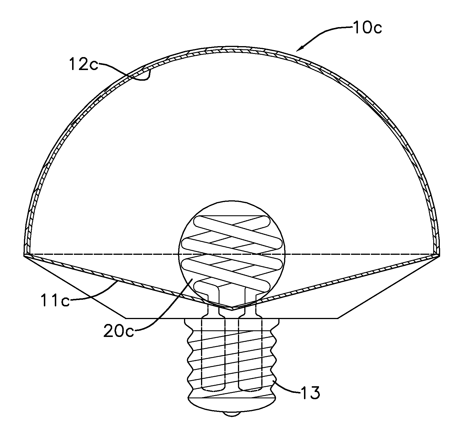
[0018]In addition, in case that no too thick fluorescent coating is needed, the fluorescent coating can be formed on the straight surface and a larger reflective surface may be additionally provided at its vertical point, so that not only the surface layer fluorescence but also the inner layer fluorescence can be taken out at the same time, making the brightness and efficiency improved with energy saving.

Problems solved by technology

The fluorescent layer can more or less convert ultraviolet light into visible light, but it is a poor material for visible light to transmit therethrough.
As a result, luminous efficiency is very low.
In general, the coated fluorescent layer is made as thin as possible to improve the light transmittance, but this causes the ultraviolet light to be insufficiently absorbed.
Accordingly, the aforementioned low luminous efficiency defect has not been solved till now.

Method used


Image

  • Brightness improving structure of light-emitting module with an optical film surface layer
  • Brightness improving structure of light-emitting module with an optical film surface layer
  • Brightness improving structure of light-emitting module with an optical film surface layer

Examples


Embodiment Construction

[0041]The above and other technical features and advantages of the present invention will be described in greater detail with reference to the drawings.

DEFINITIONS

[0042]Transparent envelope: can be composed of glass or ultraviolet-absorbing glass or other heat-resistant transparent materials, such as polycarbonate resin, etc. However, if the transparent envelope being a resin, plastic or glass that can pass through the ultraviolet light, when some long-wave pass light filter film layers only reflecting specific ultraviolet light exciting fluorescent layer due to the design, other long-wave ultraviolet lights may pass along with the visible light through the long-wave pass light filter film layers that may affect people or damage the resin itself, thereby an anti-ultraviolet film layer being required.

[0043]Optical thin film: which being a non-omni angular coating, represented by a long wave pass light filter of non-omni angular. Optical thin film light filter being composed of all di...


PUM

PropertyMeasurementUnit
transparentaaaaaaaaaa
thicknessaaaaaaaaaa
reflectanceaaaaaaaaaa

Abstract

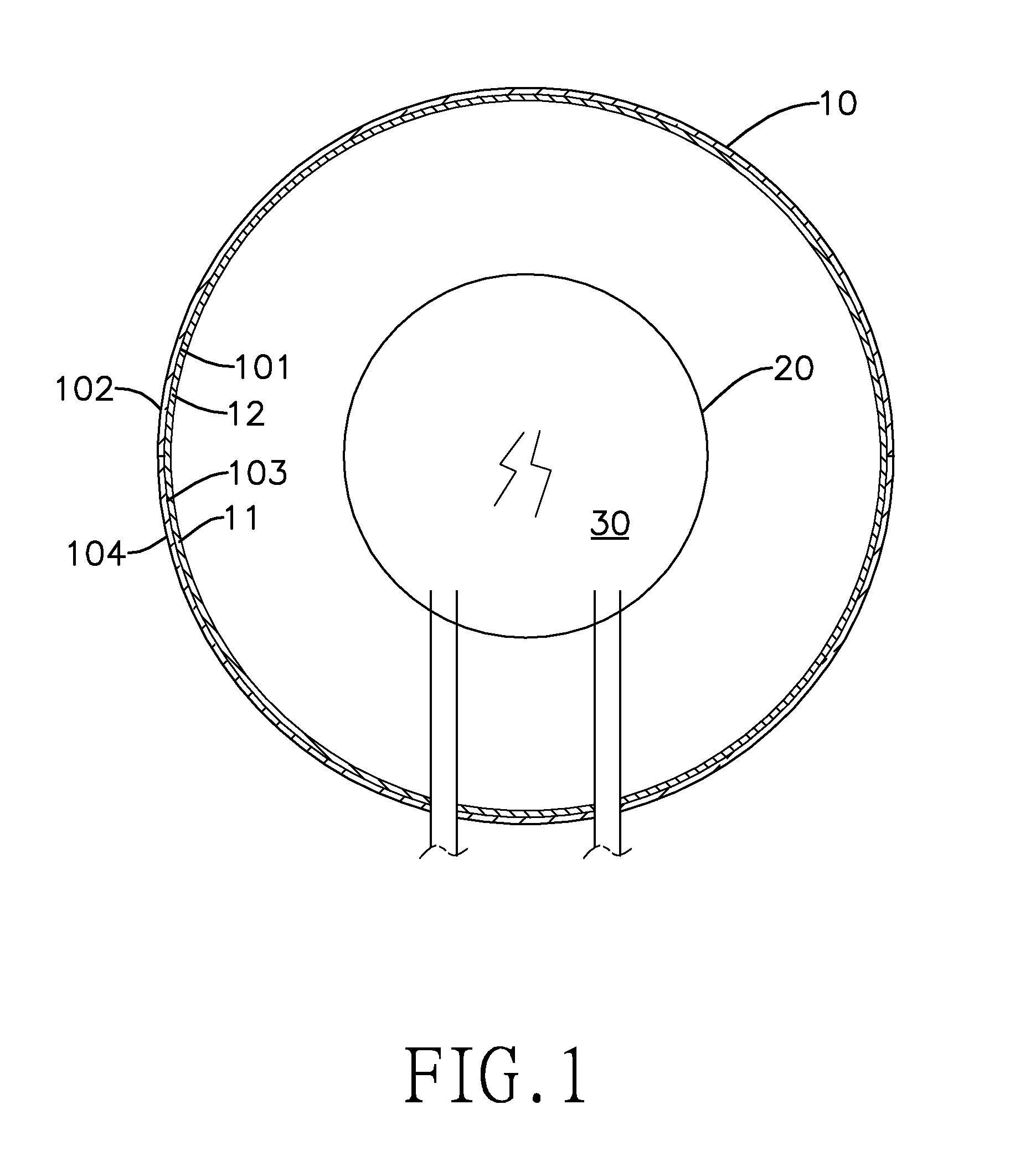
A brightness improving structure of a light-emitting module with an optical film surface layer 12, wherein a light-emitting part 20 is provided inside a transparent envelop 10 and may emit ultraviolet or blue light, the said transparent envelop 10 has first wall and second wall, first inside wall 101 and second inside wall 103 are oppositely formed inside thereof, first outside wall 102 and second outside wall 104 are oppositely formed outside thereof. The first wall is partly or entirely provided with the optical film coating 12, the optical film coating 12 may at least reflect the ultraviolet or blue light exciting fluorescent/phosphorescent light, and may pass light rays comprising visible light. A visible light layer or both the visible light layer and a reflective layer are provided on the second wall, and the said light-emitting part 20 is placed at a setting location from the envelop 10.

Description

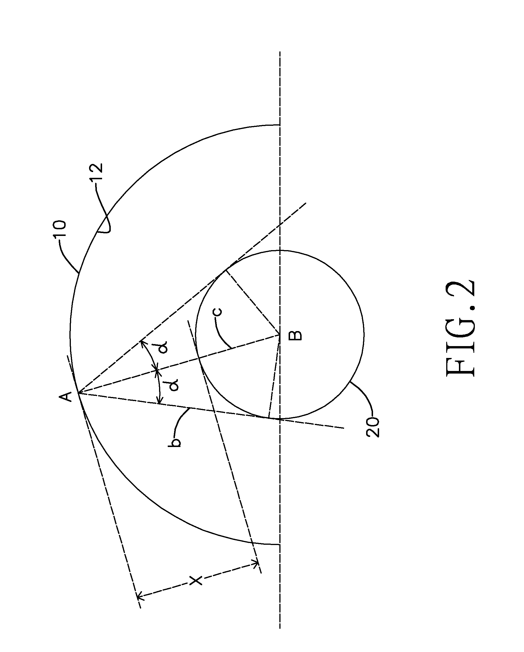
BACKGROUND OF THE INVENTION[0001]1. Field of the Invention[0002]The present invention relates to a brightness improving structure for a light-emitting module with an optical thin-film surface layer, which can notably improve the brightness of the light-emitting module at high reflectance and transmittance by spacing a light-emitting part of the light-emitting module and a reflective layer of a transparent envelop of the light-emitting module at a certain interval in a concentric circle relationship.[0003]2. Description of the Prior Arts[0004]There are many kinds of light-emitting modules known in the art, such as a daylight lamp, a fluorescent tube or the like. The fluorescent tube is mainly provided with a transparent envelop having an inside wall fully coated with a fluorescent layer. The inside of the envelop is filled with electrically excited lighting gases such as mercury and argon gas, or xenon and neon etc. mercury-free gas. When powered by a high voltage the gases inside of...

Claims


Application Information

Patent Timeline
Patent Type & Authority Applications(United States)
IPC IPC(8): H01J61/42H01J1/62F21V9/40
CPCF21K9/00H01J61/35H01J61/38F21V3/0472F21V3/0481F21K9/56F21Y2101/02F21K9/64F21Y2115/10F21K9/68F21V3/10F21V3/12
Inventor MII, JENN-WEI
Owner MII JENN WEI
Why Eureka
Try Eureka