Electronic Device Used In A Health Care Setting

Active Publication Date: 2010-08-05
CURBELL MEDICAL PRODS
12 Cites 2 Cited by

AI-Extracted Technical Summary

Problems solved by technology

Electronic devices formed according to the prior art are susceptible to damage not only from normal use, but also from liquid cleaning and disinfecting agents.
Switch membranes of the prior art, where...

Benefits of technology

[0008]In a first aspect of the invention, an electronic device for use in a health care setting generally comprises a rigid shell defining an interior space and an opening communicating with the interior space, and a rigid PCB fixed to the shell to cover the op...

Abstract

An electronic device for use in a health care setting has a rigid enclosure assembly formed by a rigid shell and a rigid printed circuit board carrying circuitry for operating the device. A switch dome layer and an overlay are independently attached to the device but not to each other, whereby the overlay may be removed without disturbing the dome layer and a better tactile response is achieved.

Application Domain

Technology Topic

Printed circuit boardCare setting +2

Image

  • Electronic Device Used In A Health Care Setting
  • Electronic Device Used In A Health Care Setting
  • Electronic Device Used In A Health Care Setting

Examples

  • Experimental program(1)

Example

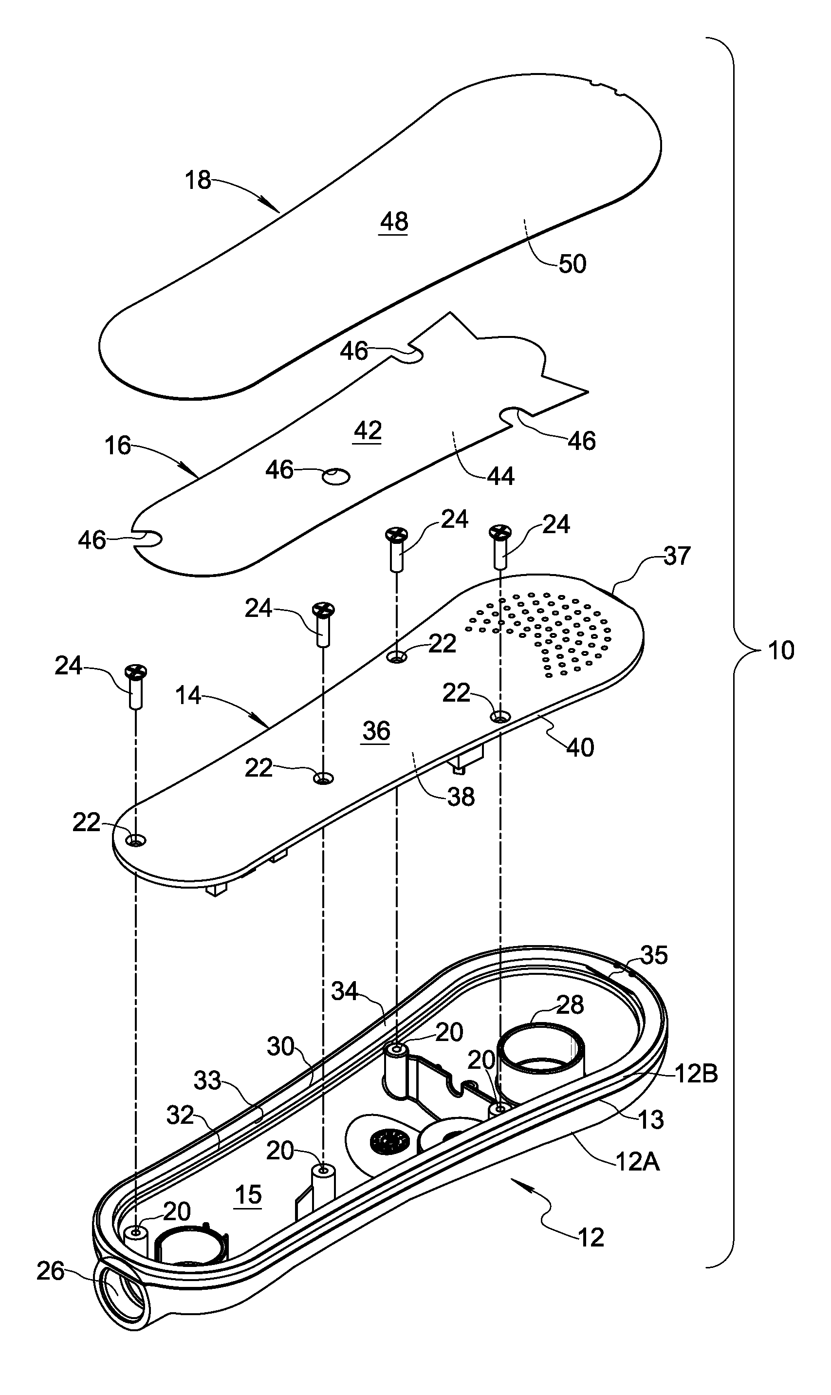
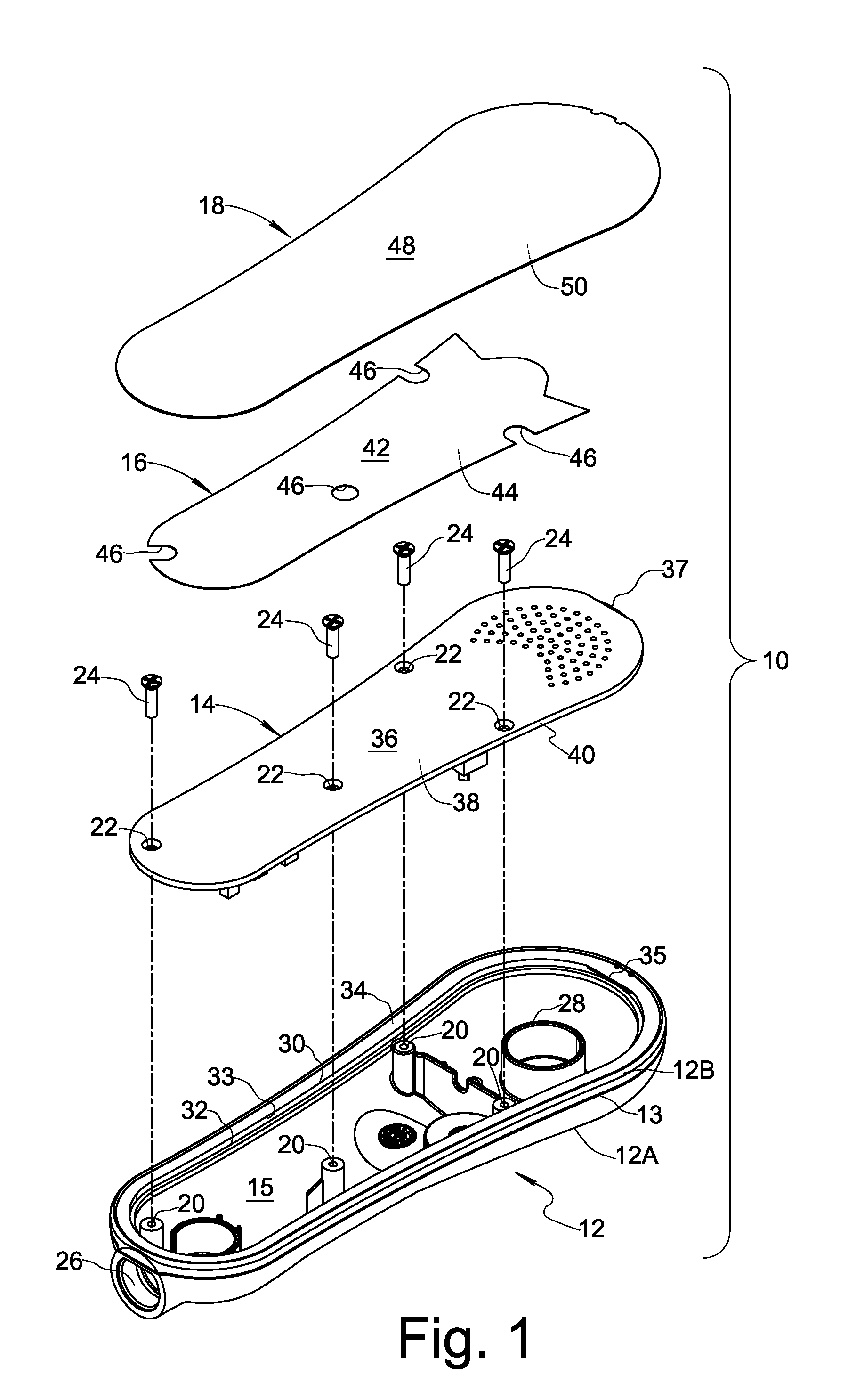
[0017]FIG. 1 shows, in exploded view, a pillow speaker 10 formed in accordance with an embodiment of the present invention. Pillow speaker 10 is an electronic device for use in a health care setting, such as a hospital, nursing home, clinic, or similar environment. While the present invention is described with respect to a pillow speaker, it will be understood that other types of electronic devices used in health care settings may be constructed as taught herein. Examples of other types of electronic devices to which the present invention may be applied include, without limitation, handheld pendants, bed rails, wall plates, and call cords where a user interface is required.
[0018]Pillow speaker 10 generally comprises a rigid shell 12, a rigid PCB 14, a dome layer 16, and an overlay 18. Shell 12 defines an interior space 15 and an opening 30 communicating with the interior space. Shell 12 may include a plurality of fastener receptacles 20, a cord passageway 26 through which wires may pass to reach interior space 15, a speaker mount 28 for receiving an audio speaker (not shown), a support surface 32 for supporting PCB 14, an inner surface 33 generally orthogonal to support surface 32 in the region of the support surface, and a rim surface 34 around opening 30. Shell 12 may also include a retainer tab 35 protruding from rim surface 34 overtop support surface 32.
[0019]In the embodiment shown in FIG. 1, shell 12 is manufactured from a first shell portion 12A and a second shell portion 12B. The first and second shell portions 12A, 12B may each be molded of plastic, and then attached to one another to form rigid shell 12. It is advantageous that the shell be free of small openings through which moisture may penetrate. Shell portions 12A and 12B may be ultrasonically welded together, as evidenced by weld seam 13, to form rigid shell 12. Alternatively, a moisture sealing adhesive may be used to bond the shell portions together. Rigid shell 12 may also be formed in unitary fashion as a single piece of molded plastic. 100151 Rigid PCB 14 is fixed to shell 12 by fasteners 24 extending through respective fastener holes 22 through PCB 14 and engaging fastener receptacles 20. Fasteners 24 may be threaded fasteners, and fastener receptacles 20 may be internally threaded to mate with a corresponding fastener 24. PCB 14 covers opening 30 and includes electronic circuitry (not shown) for operation of pillow speaker 10. In accordance with a first aspect of the present invention, shell 12 and PCB 14 cooperate with one another to form a rigid enclosure assembly for pillow speaker 10.
[0020]PCB 14 includes an inward surface 38 contacting support surface 32 of shell 12. As shown in FIG. 1, support surface 32 may be recessed relative to rim surface 34, such that a peripheral edge 40 of PCB 14 opposes inner surface 33 of the shell 12. In this arrangement, PCB acts as a rigid member providing structural integrity to the rigid enclosure assembly. For example, if pillow speaker 10 is subjected to an impact force as may happen if pillow speaker 10 is dropped to the floor, inwardly directed force applied to the outside of shell 12 may be opposed by rigid PCB 14. Applicants have found that a PCB thickness of 3.5 mm or greater will provide the rigid enclosure assembly with suitable structural integrity to withstand forces commonly encountered during normal use of the pillow speaker device. However, it will be understood that thickness is but one dimension of PCB 14, and PCB's that are less than 3.5 mm in thickness may be suitable for some applications. The word “rigid,” as used herein to modify PCB, is intended to distinguish from flexible PCBs now on the market, and does not imply a minimum thickness requirement.
[0021]In the embodiment of FIG. 1, retainer tab 35 is arranged to engage a recessed portion 37 of an outward surface 36 of PCB 14. Retainer tab 35 and recessed portion 37 may be at corresponding longitudinal ends of shell 12 and PCB 14, respectively, whereby the retainer tab pushes down on the end of the circuit board such that an axial tension force is created in fasteners 24 when the fasteners are tightened.
[0022]Referring also now to FIGS. 2 and 3, it will be seen that outward surface 36 of PCB 14 may include one or more switch traces 54 associated with pushbutton control switches enabling a user to enter commands to the device. Dome layer 16 is arranged adjacent outward surface 36 of PCB 14. Dome layer 16 includes a nonconductive sheet 42 and at least one conductive switch dome 56 attached to the sheet. Sheet 42 may be a thin polyester layer with adhesive only on its inward surface 44 (FIG. 1) to adhere the sheet to outward surface 36 of PCB 14 as shown in FIG. 3. Each switch dome 56 is applied to adhesive surface 44 of sheet 42 and positioned to register with a corresponding switch trace 54 on the PCB, wherein the switch dome is operable to close the switch trace by applying pressure to the switch dome.
[0023]Overlay 18 is arranged adjacent dome layer 16 and covers the dome layer to provide switch button embossing, switch graphics, and electrical isolation. Overlay 18 may be a polyester layer having an external surface 48 and an internal surface 50 (FIG. 1). Overlay 18 may have an electrical insulation voltage rating greater than 25 kV, however this property is subject to design choice depending upon the specific application. Overlay 18 includes a switch graphic 58 on external surface 48 at a location corresponding to an associated switch dome 56 of the dome layer. The switch graphic 58 may indicate a function of the switch button to the user, and may include alphanumeric characters or a word. In a commercial embodiment of the invention, the overlay 18 is embossed in the region of each switch graphic 58 and switch dome 56 to provide a more user-friendly tactile push button. The embossing may include Braille characters to assist blind patients.
[0024]As seen in FIG. 4, the internal surface 50 of overlay 18 may include an adhesive portion 50A and a non-adhesive portion 50B. Adhesive portion 50A adheres to shell 12 and/or PCB 14, but does not adhere to dome layer 16. Dome layer 16 is covered by non-adhesive portion 50B, such that overlay 18 and dome layer 16 remain unattached to one another. Accordingly, overlay 18 may be fixed to the outward surface 36 of PCB 14 by adhesive at a portion of outward surface 36 not covered by dome layer 16. As represented in FIG. 5, adhesive portion 50A may extend beyond a peripheral region of PCB 14 so that it adheres to both the peripheral region of the PCB and to the rim surface 34 of shell 12.
[0025]The present invention extends to a method of making electronic device 10. The method generally comprises the steps of providing rigid shell 12 defining interior space 15 and opening 30 communicating with the interior space; providing rigid PCB 14 including electronic circuitry for operation of the device; and fixing the PCB to the shell such that the PCB covers the shell opening, wherein the shell and the PCB cooperate with one another to form a rigid enclosure assembly for the electronic device. A peripheral edge of the PCB may be arranged to oppose an inner surface of the shell.
[0026]According to another aspect of the inventive method, PCB 14 includes outward surface 36 having switch trace 54 thereon, and the inventive method further comprises the steps of providing dome layer 16 including nonconductive sheet 42 and switch at least one dome 56 attached to the sheet; fixing dome layer 16 to outward surface 36 of PCB 14 such that the switch dome is operable to close the switch trace; providing overlay 18 overlay including at least one switch graphic 58; and fixing overlay 18 to at least one of the shell 12 and the outward surface 36 of PCB 14 such that the switch graphic 58 is at a location corresponding to the switch dome 56, wherein the overlay 18 is unattached to dome layer 16. The dome layer 16 and the overlay 18 may be fixed to the outward surface 36 of PCB 14 by adhesive at different portions of the outward surface 36. Overlay 18 may also be fixed to shell 12 by adhesive. The steps mentioned in this paragraph also represent an improved method of making electronic device 10 for a health care setting, independently of the steps for constructing the rigid enclosure assembly described in the immediately preceding paragraph.
[0027]The present invention eliminates the need for a second rigid piece to form an enclosure assembly by using the PCB for structural function in addition to electronic function.
[0028]Moreover, the use of a dome layer and an overlay that are unattached to one another reduces cost, improves tactile feel of the buttons, and facilitates servicing of the device. Cost is reduced due to the fact that the dome layer 16 carries only the metal switch domes 56, whereby the dome layer may be configured for use with a large number of corresponding overlays 18. This reduces the number of different part numbers for manufacturing specifications. Tactile feel is improved because the user feels the entire tactile feel of the metal dome 56 itself, which was not the case with prior art switch membranes where the overlay and switch dome were physically coupled to one another. Serviceability is improved because only the overlay 18 needs to be discarded and replaced when the device is opened up, and the dome layer 16 including costly metal domes 56 can remain and be reused.
[0029]With regard to serviceability, the present invention is further embodied by an improved method for servicing an electronic device of a type comprising a PCB including a switch trace, a switch dome operable to close the switch trace, and an overlay including a switch graphic at a location corresponding to the switch dome. The servicing method of the present invention comprises the steps of removing the overlay 18 from the device 10 without removing the switch dome 56 from the device 10; performing a service operation; and fixing a replacement overlay different from the removed overlay on the device overtop the original switch dome 56.
[0030]Modifications and other embodiments of the inventions set forth herein will be apparent to one skilled in the art to which these inventions pertain in light of teachings presented in the present specification. Therefore, the inventions are not to be limited to the specific embodiments disclosed, and modifications and other embodiments are intended to be included within the scope of the appended claims.
Parts List
[0031]10 Electronic device (pillow speaker)
[0032]12 Shell
[0033]12A First shell portion
[0034]12B Second shell portion
[0035]13 Ultrasonic weld seam
[0036]14 Printed circuit board (PCB)
[0037]15 Interior space of shell
[0038]16 Dome layer
[0039]18 Overlay
[0040]20 Fastener receptacles
[0041]22 Fastener holes through PCB
[0042]24 Fasteners
[0043]26 Cord passageway
[0044]28 Speaker mount
[0045]30 Shell opening
[0046]32 Support surface for PCB
[0047]33 Inner surface of shell
[0048]34 Rim surface of shell
[0049]35 Retainer tab
[0050]36 Outward surface of PCB
[0051]36A Portion of outward surface of PCB not covered by dome layer
[0052]38 Inward surface of PCB
[0053]40 Peripheral edge of PCB
[0054]42 Nonconductive sheet of dome layer
[0055]44 Adhesive surface of nonconductive sheet
[0056]46 Cut-out regions of nonconductive sheet
[0057]48 External surface of overlay
[0058]50 Internal surface of overlay
[0059]50A Adhesive portion of internal surface of overlay
[0060]50B Non-adhesive portion of internal surface of overlay
[0061]54 Switch traces on outward surface of PCB
[0062]56 Switch domes of dome layer
[0063]58 Switch graphics of overlay

PUM

PropertyMeasurementUnit
Thickness0.0035m
Adhesivity
tensileMPa
Particle sizePa
strength10

Description & Claims & Application Information

We can also present the details of the Description, Claims and Application information to help users get a comprehensive understanding of the technical details of the patent, such as background art, summary of invention, brief description of drawings, description of embodiments, and other original content. On the other hand, users can also determine the specific scope of protection of the technology through the list of claims; as well as understand the changes in the life cycle of the technology with the presentation of the patent timeline. Login to view more.

Similar technology patents

Method and devices for cell loss detection in ATM telecommunication devices

InactiveUS6763024B1Avoids needData switching by path configurationTime-division multiplexing selectionTelecommunications DeviceCell loss
Owner:ALCATEL LUCENT CANADA +1

Classification and recommendation of technical efficacy words

Why Eureka
Try Eureka