Power distribution unit monitoring network and components

Inactive Publication Date: 2010-08-05
LEVITON MFG
View PDF44 Cites 130 Cited by
  • Summary
  • Abstract
  • Description
  • Claims
  • Application Information

AI Technical Summary

Problems solved by technology

This can be an inefficient use of resources which requires more wir

Method used


Image

  • Power distribution unit monitoring network and components
  • Power distribution unit monitoring network and components
  • Power distribution unit monitoring network and components

Examples


Embodiment Construction

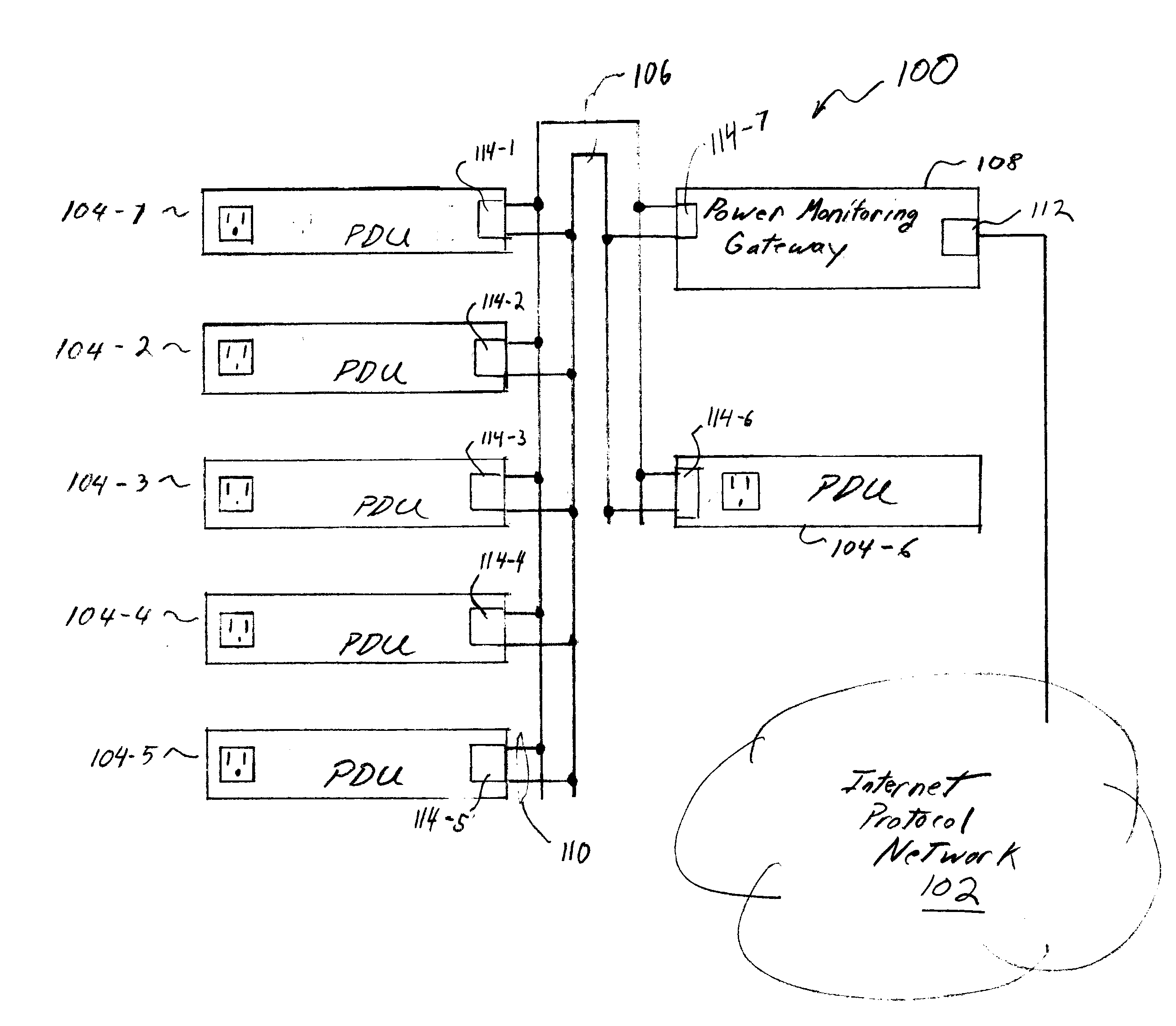
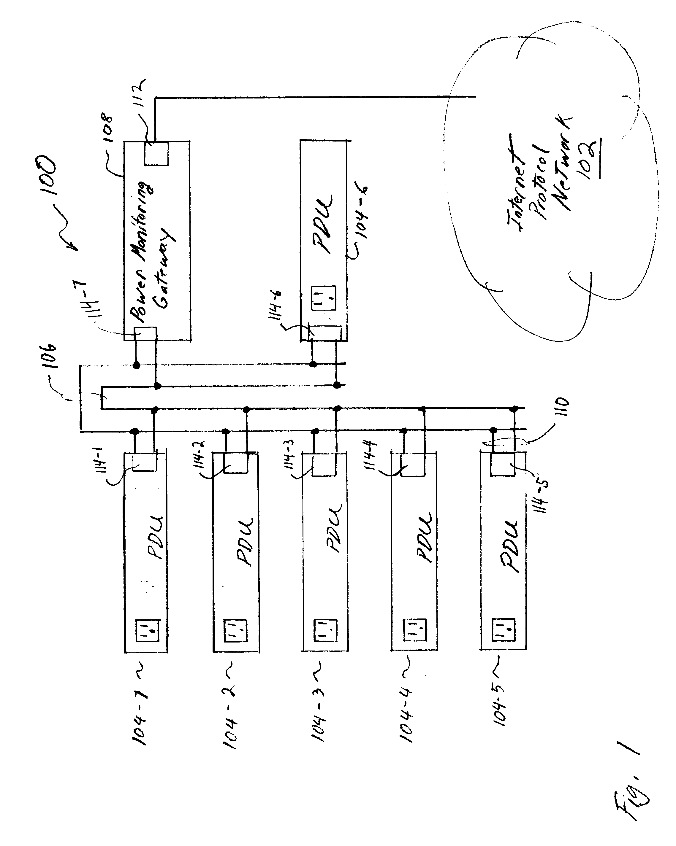
[0012]FIG. 1 is a schematic drawing of a power distribution monitoring network 100 and its components. The power monitoring network 100 is configured to monitor power loading in various devices, generate power loading information, send that power loading information to a gateway which in turn sends power loading information over an internet to a central monitoring point. Some of the components of the power monitoring network 100 may connect with an IP based network (“IP network”) 102. The power monitoring network 100 comprises a plurality of power distribution units (PDUs) 104-1 through 104-6, a power monitoring gateway 108 and a wire pair 106. All of the devices in the power monitoring network 100, both PDUs 104 and power monitoring unit 108, each have a wired communication port 114. Each wired communication port 114 in turn has a transmitter and receiver, both connected to a stub 110 conductor pair. The PDUs 104 and the power monitoring gateway 108 are described in greater detail ...


PUM


Abstract

A system to monitor power loading in a plurality of power distribution units. The system includes a power monitoring gateway with a port configured to communicate with an internet protocol network using an internet protocol address. The power monitoring gateway is also configured to communicate with the plurality of power distribution units through a communication link that does not use internet protocol addressing. The communication link in some embodiments is a wireless link. In other embodiments, the communication link uses a single pair of wires with the power monitoring gateway and the power distribution units configured in a daisy chain topology.

Description

BACKGROUND OF THE INVENTION[0001]1. Field of the Invention[0002]The present invention is directed generally to power distribution systems within a telecommunications facility or data center. In particular, the present invention is directed to networks to monitor power distribution systems.[0003]2. Description of the Related Art[0004]Power distribution units (PDU) are a necessary part of any data center or telecommunications facility. Mounted in an equipment rack, a PDU distributes power, typically AC power, to computing and communications equipment in the rack. Traditionally, PDUs have been simple devices. Typical PDUs included power receptacles, power inputs, and a few breakers and manually operated switches.[0005]More recently, monitoring intelligence has been added to some PDUs. Some PDUs now have sensors to monitor a PDU load bank, including sensors for current, voltage and power. Some PDUs have displays that display power loading information. Some PDUs have network connections ...

Claims


Application Information

Patent Timeline
IPC IPC(8): G01R21/00
CPCG01R22/063
Inventor BROWN, KENNETHRAMIREZ, CARLOS G.GUYMON, MARK A.SCHOEPF, THOMAS RICHARD
Owner LEVITON MFG
Why Eureka
Try Eureka