
Computer system and method for overclocking the same

a computer system and overclocking technology, applied in the field of computer system and overclocking the same, can solve the problems of user inconvenience, user's inability to use overclocking via software setting, and user's inability to incidentally damage other elements, etc., to achieve convenient operation of the computer system, simplify the overclocking procedure, and avoid the effect of tedious setting steps

Inactive Publication Date: 2010-08-05
ASUSTEK COMPUTER INC
View PDF8 Cites 8 Cited by
  • Summary
  • Abstract
  • Description
  • Claims
  • Application Information

AI Technical Summary

Benefits of technology

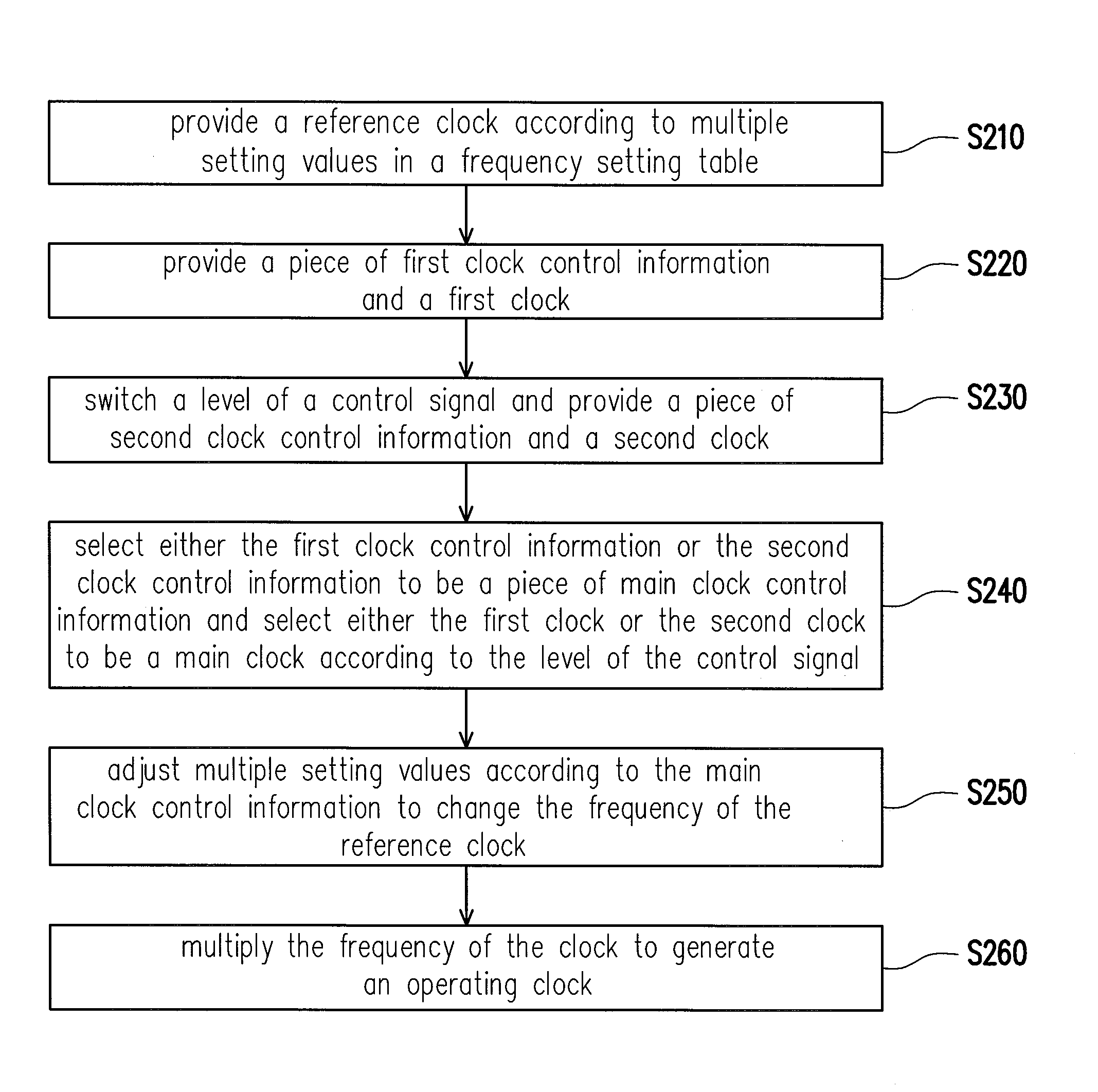
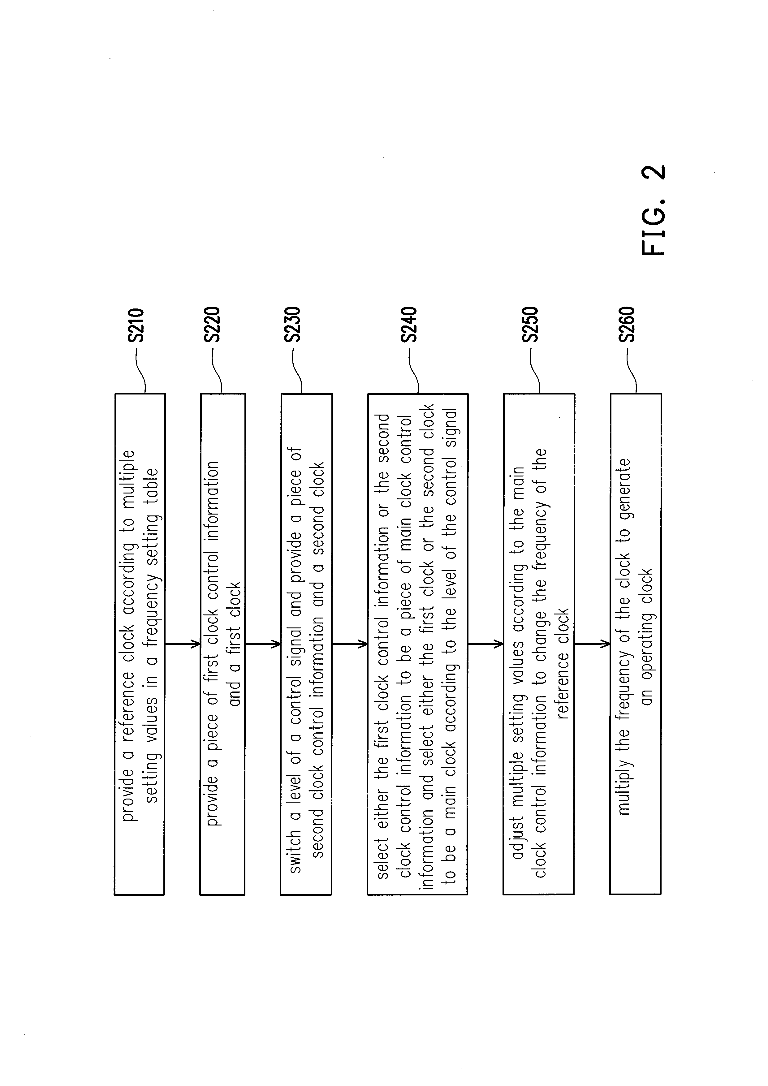
[0010]The invention provides a method for overclocking a computer system which may overclock a computer system by hardware control or software setting manner. With using the hardware control manner, the tedious setting steps in the software setting process are avoided.
[0017]Based on the above, in the invention, the multiplexing unit is used to switch the control authority of the clock generator between the system chipset and the controller to perform overclocking by the software setting manner or the hardware control manner. Furthermore, besides providing multiple overclocking manners, the invention also simplifies overclocking procedure and dispense with tedious setting steps. Thus, the user may operate the computer system more conveniently.

Problems solved by technology

However, the user may feel inconvenient in this manner, and when disassembling the case and adjusting the motherboard, the user would possible incidentally damage other elements.
However, regardless of overclocking in the BIOS setting mode or under the OS by executing applications, the overclocking performed via the software setting are mostly too complex to use, since the overclocking process requires a series of operation settings.

Method used


Image

  • Computer system and method for overclocking the same
  • Computer system and method for overclocking the same
  • Computer system and method for overclocking the same

Examples


Embodiment Construction

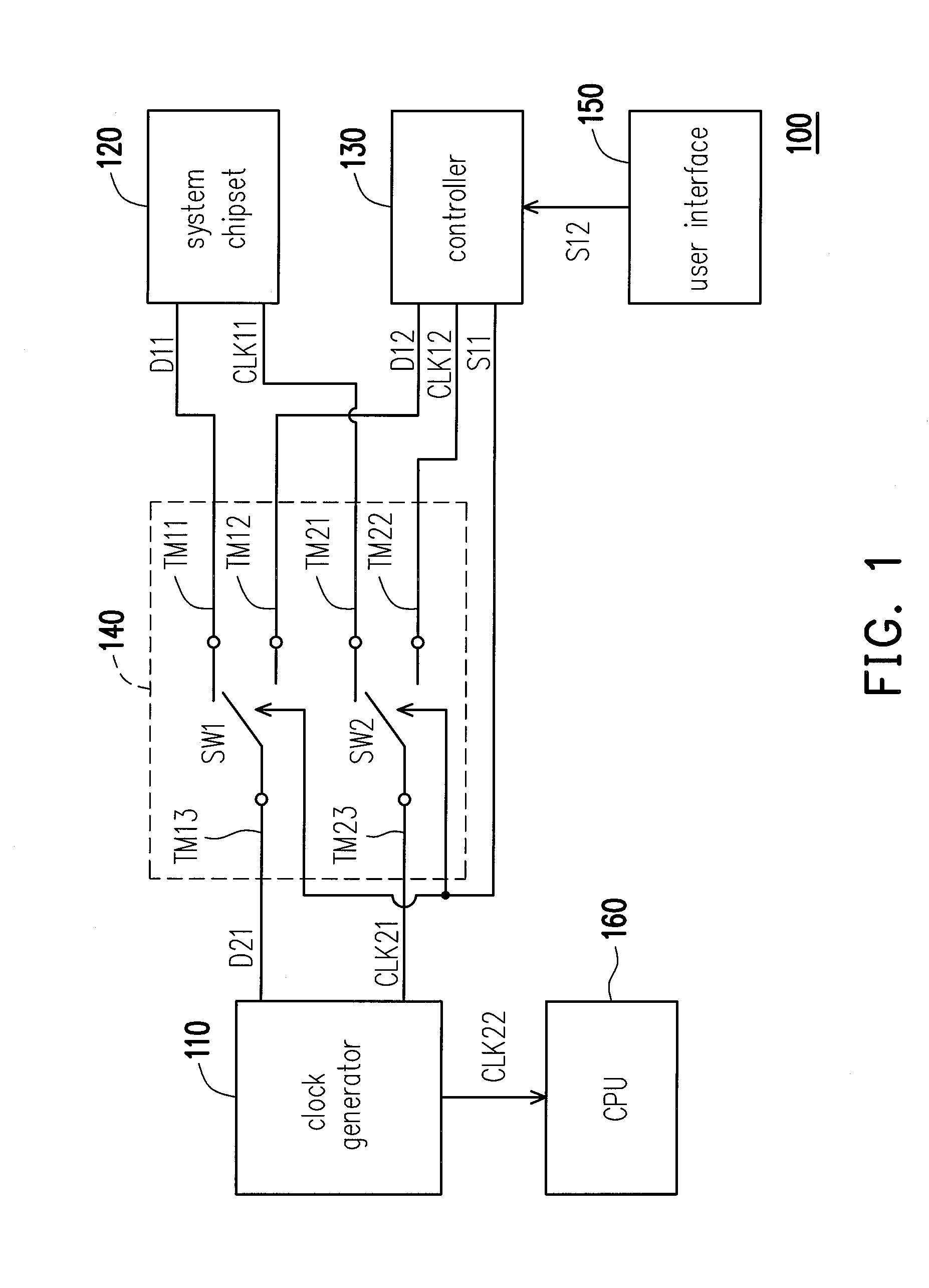
[0020]FIG. 1 is a block diagram showing a circuit of a computer system in an embodiment of the invention. As shown in FIG. 1, the computer system 100 includes a clock generator 110, a system chipset 120, a controller 130, a multiplexing unit 140, a user interface 150 and a CPU 160.

[0021]In the whole operation, the clock generator 110 generates a reference clock CLK 22 according to a plurality of setting values in a frequency setting table. In another aspect, the CPU 160 receives the reference clock CLK 22 and multiplies the frequency of the reference clock CLK 22 to generate an operating clock. In other words, the computer system 100 may change the operating clock of the CPU 160 via change the reference clock CLK 22. Therewith, the processing speed of the CPU 160 is adjusted.

[0022]For setting the reference clock CLK 22, the clock generator 110 adjusts a plurality of setting values in the frequency setting table according to a main clock CLK 21 and a piece of main clock control infor...


PUM


Abstract

A computer system includes a clock generator, a system chipset, a controller and a multiplexing unit. The clock generator generates a reference clock according to a plurality of setting values in a frequency setting table. The system chipset generates a piece of first clock control information and a first clock. The controller is used to switch the level of the control signal and generates a piece of second clock control information and a second clock. The multiplexing unit is used to receive the control signal to select either the first clock control information or the second clock control information to be a piece of main clock control information and select either the first clock or the second clock to be a main clock. The clock generator adjusts the setting values according to the main clock control information and the main clock to change the frequency of the reference clock.

Description

CROSS-REFERENCE TO RELATED APPLICATION[0001]This application claims the priority benefit of Taiwan application serial no. 98103197, filed on Feb. 2, 2009. The entirety of the above-mentioned patent application is hereby incorporated by reference herein and made a part of specification.BACKGROUND OF THE INVENTION[0002]1. Field of the Invention[0003]The invention relates to a computer system and a method for overclocking the same and, more particularly, to a computer system which may perform the overclocking by hardware control or software setting manner and a method for overclocking the same.[0004]2. Description of the Related Art[0005]The computer system usually has a clock generator to provide different operating clocks for a central processing unit (CPU) on a motherboard. When setting the operating clock of the CPU, the user usually increases the frequency of the operating clock of the CPU to a value higher than a preset value set by the manufacturer to save the expense, which is ...

Claims


Application Information

Patent Timeline
Patent Type & Authority Applications(United States)
IPC IPC(8): G06F1/06
CPCG06F1/08
Inventor SUN, PEI-HUA
Owner ASUSTEK COMPUTER INC
Learn More