Hydraulic Pump Unit
a pump unit and hydraulic technology, applied in the direction of fluid couplings, gearings, servomotors, etc., can solve the problems of large manual operation power and manual operation amount for the travel, fluctuation of the output amount of the hydraulic motor unit, and difficulty in miniaturizing the controlling member, so as to reduce the capacity adjusting mechanism and manual operation. the effect of operation
- Summary
- Abstract
- Description
- Claims
- Application Information
AI Technical Summary
Benefits of technology
Problems solved by technology
Method used
Image
Examples
embodiment 1
[0047]Hereinafter, a preferred embodiment of a hydraulic pump unit according to the present invention will be described referring to the accompanying drawings.
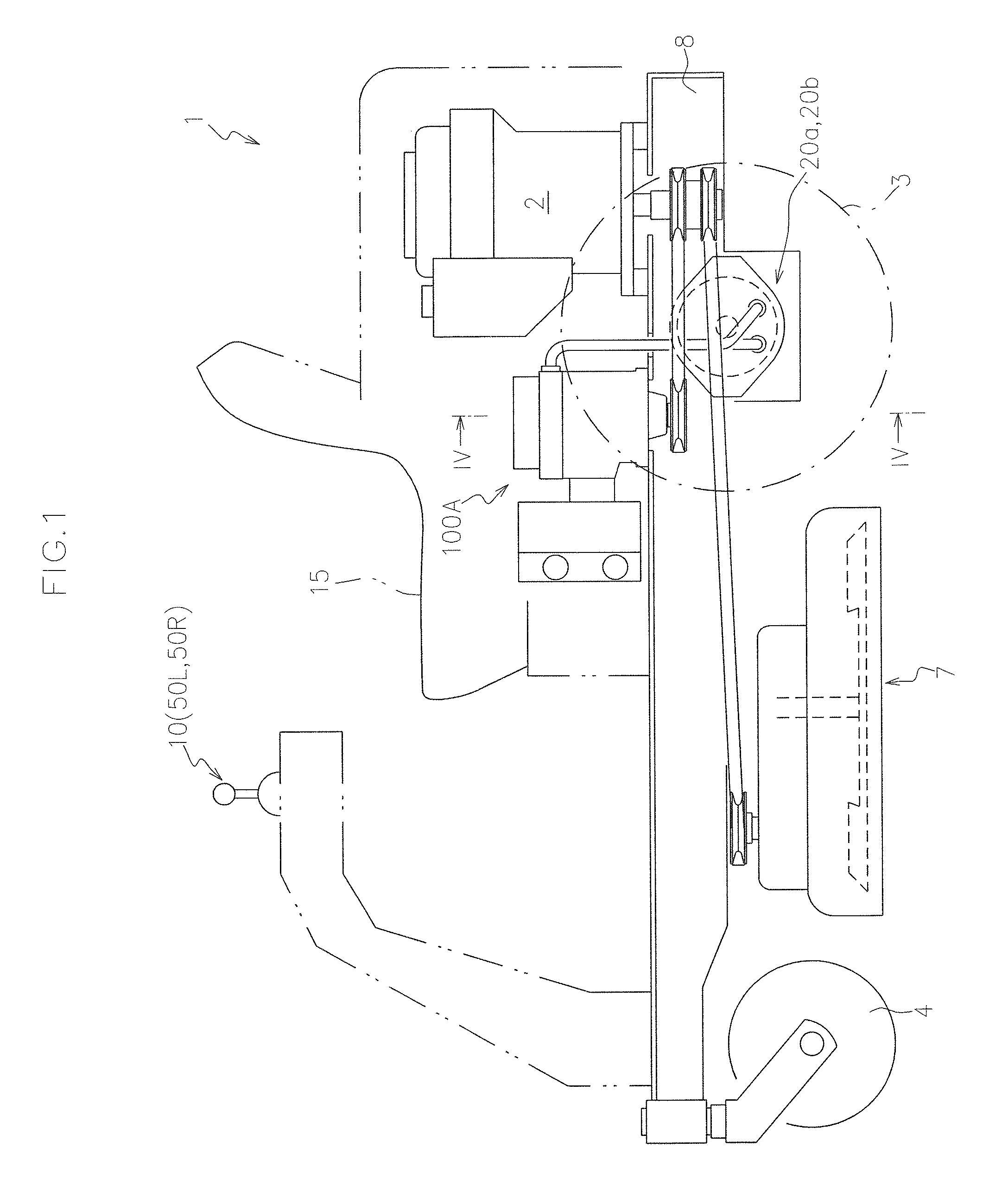
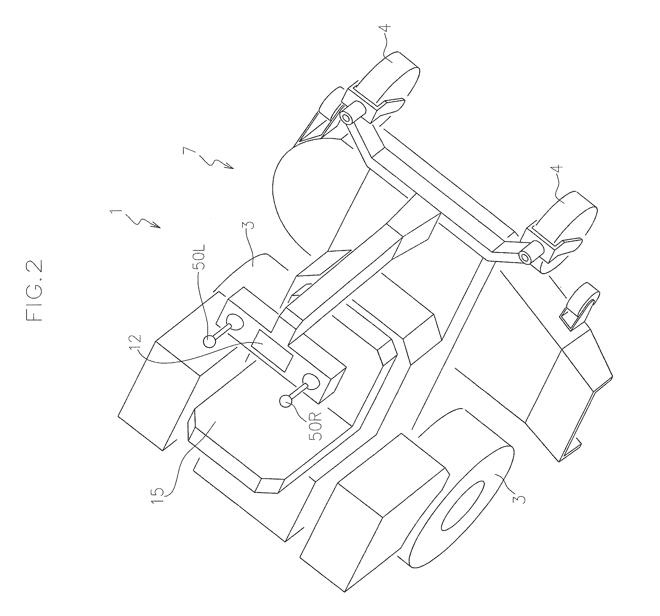
[0048]FIGS. 1 and 2 show a schematic side view and a schematic perspective view of a working vehicle 1 to which a hydraulic pump unit 100A according to the present embodiment is applied, respectively.
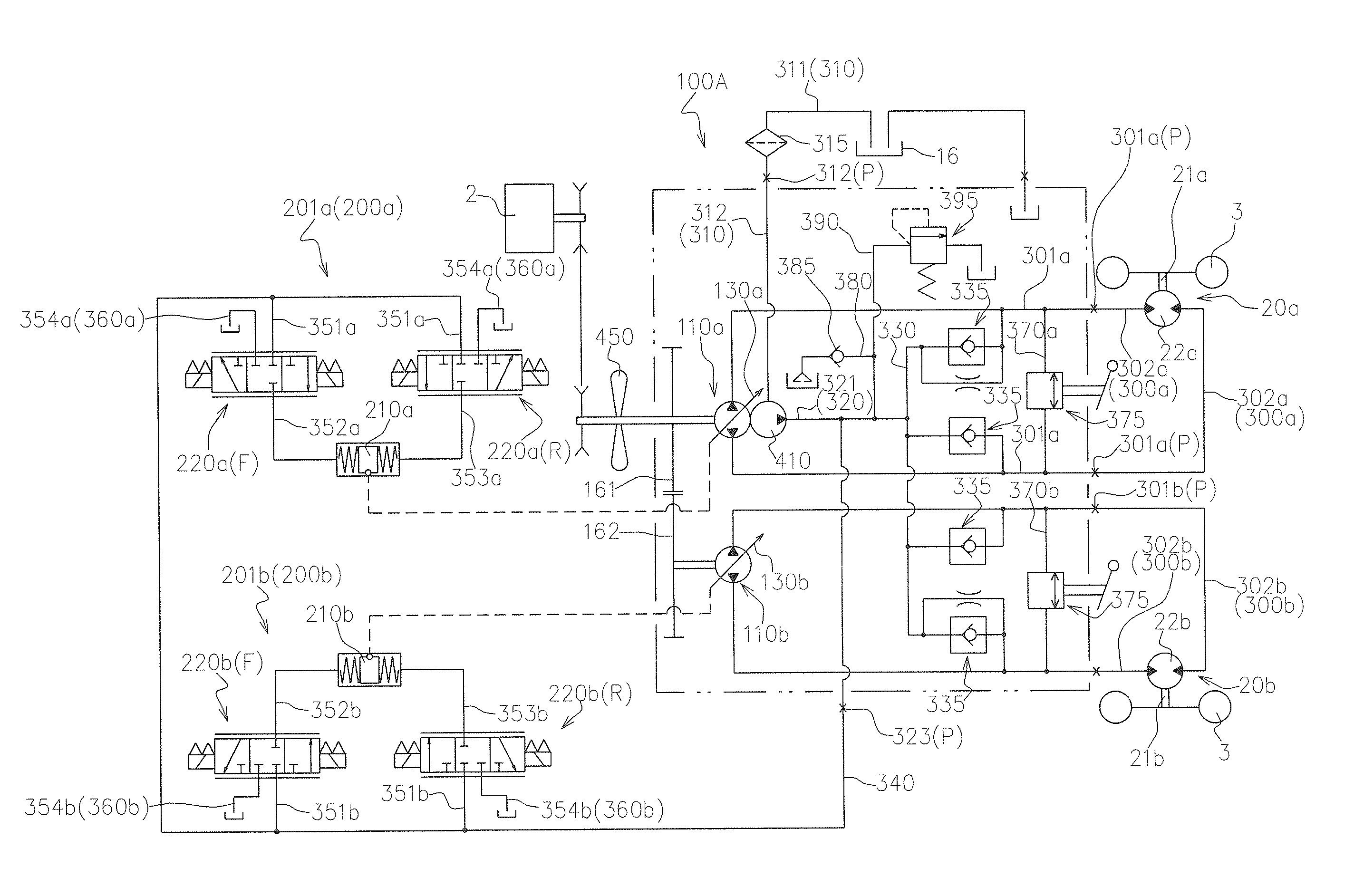
[0049]FIG. 3 shows a hydraulic circuit diagram of the working vehicle 1.
[0050]As shown in FIGS. 1 to 3, the working vehicle 1 is provided with a vehicle frame 8, a driving source 2 supported by the vehicle frame 8, a pair of right and left driving wheels 3 (rear wheels in the present embodiment), caster wheels 4 (a pair of front wheels in the present embodiment), first and second hydraulic motor units 20a, 20b for respectively and independently driving the pair of driving wheels 3, a hydraulic pump unit 100A of variable displacement type according to the present embodiment, and a travel operation mechanism 10 for changing the supp...
embodiment 2
[0169]Hereinafter, another embodiment of the hydraulic pump unit according to the present invention will be described referring to the accompanying drawings.
[0170]FIG. 11 shows a sectional view taken in a line orthogonal to the pump shafts of a hydraulic pump unit 100B according to the present embodiment.
[0171]As shown in FIG. 11, the hydraulic pump unit 100B according to the present embodiment is different from the hydraulic pump unit 100A mainly in that the piston accommodating chamber is provided in a wall portion of a pump case.
[0172]Therefore, the same members as the embodiment 1 in the figures are designated by the same numerals, and the detailed description thereof are omitted.
[0173]Specifically, the hydraulic pump unit 100B according to the present embodiment has a case body 170B instead of the case body 170 in the hydraulic pump unit 100A.
[0174]As shown in FIG. 11, the case body 170B is constituted so that the peripheral wall defines the first and second piston accommodatin...
embodiment 3
[0178]Hereinafter, still another embodiment of the hydraulic pump unit according to the present invention will be described referring to the accompanying drawings.
[0179]FIG. 12 shows a longitudinal sectional view taken in a line along pump shafts of the hydraulic pump unit 1000 according to the present embodiment.
[0180]The same members as those of the embodiment 1 or 2 are designated by the same numerals, and the detailed description thereof are omitted.
[0181]As shown in FIG. 12, the hydraulic pump unit 100C according to the present embodiment is provided with pump cases which respectively correspond to the first and second hydraulic pump bodies 110a, 110b.
[0182]That is, the hydraulic pump unit 100C is provided with a pair of pump cases 120C for respectively accommodating the first hydraulic pump body 110a and the second hydraulic pump body 110b. The pair of pump cases 120C are arranged in parallel.
[0183]The hydraulic pump unit 100C may be provided with a pair of pulleys 161C respe...
PUM
 Abstract
Description
Claims
Application Information
 - R&D
- Intellectual Property
- Life Sciences
- Materials
- Tech Scout
- Unparalleled Data Quality
- Higher Quality Content
- 60% Fewer Hallucinations
Browse by: Latest US Patents, China's latest patents, Technical Efficacy Thesaurus, Application Domain, Technology Topic, Popular Technical Reports.
© 2025 PatSnap. All rights reserved.Legal|Privacy policy|Modern Slavery Act Transparency Statement|Sitemap|About US| Contact US: help@patsnap.com


