
Non-pneumatic tire and its manufacturing method

a manufacturing method and tire technology, applied in the field of non-pneumatic tires, can solve the problems of not having an excellent performance of pneumatic tires, tire is heavy and rigid, and does not have a shock absorption performance, etc., to improve the reinforcing effect and durability, improve the rigidity fluctuation, and improve the durability

Inactive Publication Date: 2010-08-12
TOYO TIRE & RUBBER CO LTD
View PDF18 Cites 109 Cited by
  • Summary
  • Abstract
  • Description
  • Claims
  • Application Information

AI Technical Summary

Benefits of technology

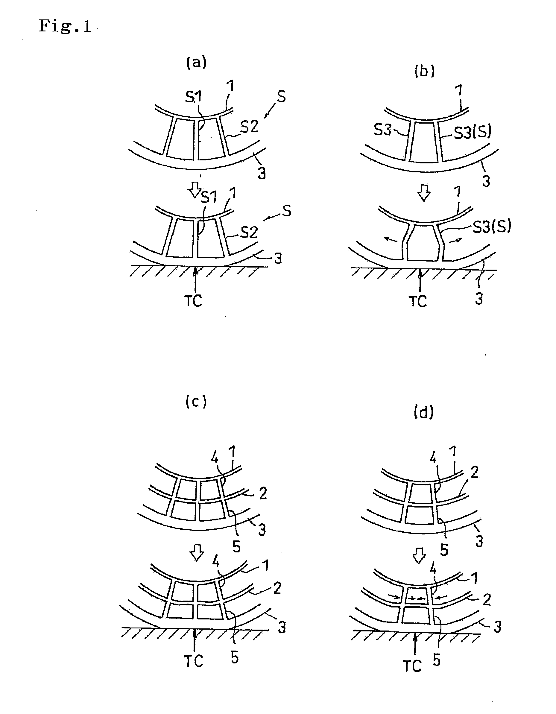
[0012]In this case, in the non-pneumatic tire of the patent publication 1, there is described a matter that a load from an axle is supported and a power is transmitted with a tensile force of the web spoke. In this case, a rigidity fluctuation can be improved in a theoretical sense by lowering a rigidity with respect to a compression force of the web spoke. However, since a large problem is generated in a durability in the case of transmitting the power from the axle only by the tensile force of the web spoke, a certain level of rigidity with respect to the compression force is necessary in the web spoke.
[0036]In the structure mentioned above, it is preferable to alternately pass the reinforcing fiber through the space portion corresponding to the intermediate annular portion and the space portion corresponding to the outer annular portion while going through the space portion corresponding to the outer coupling portion, at a time of arranging the reinforcing fiber in the space portion. In accordance with this manufacturing method, it is possible to arrange the reinforcing fiber seamlessly in the outer coupling portion, the intermediate annular portion and the outer annular portion by the simple steps, and it is possible to further improve the reinforcing effect and the durability.

Problems solved by technology

As a conventional non-pneumatic tire, for example, a solid tire, a spring tire, a cushion tire and the like exist, however, they do not have an excellent performance of the pneumatic tire.
For example, the solid tire and the cushion tire support the load based on a compression of a ground portion, however, this kind of tire is heavy and rigid, and does not have a shock absorbing performance like the pneumatic tire.
Further, in the non-pneumatic tire, it is possible to improve the cushion performance by enhancing elasticity, however, there is a problem that such a load support performance or durability of the pneumatic tire is deteriorated.

Method used


Image

  • Non-pneumatic tire and its manufacturing method
  • Non-pneumatic tire and its manufacturing method
  • Non-pneumatic tire and its manufacturing method

Examples


example 1

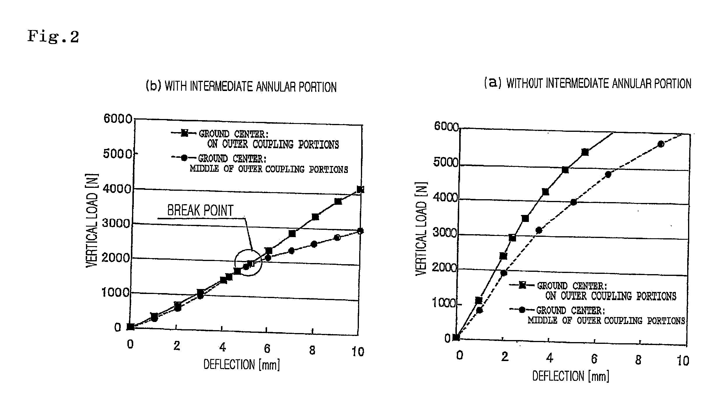
[0138]There was produced a non-pneumatic tire which is provided with a support structure body having an inner ring, an intermediate ring, an outer ring, inner spokes (standing erect in a radial direction) and outer spokes (standing erect in a radial direction) coupling the respective rings, two layers of reinforcing layers provided in an outer periphery thereof, and a tread rubber, in accordance with dimensions, physical properties and the like shown in Table 1, and the performances mentioned above were evaluated. The results are shown in Table 1 in conjunction therewith. Further, the result of the rigidity fluctuation test is shown in FIG. 6.

[0139]In this case, the formation of the support structure body was executed by using a metal die having a space portion corresponding to the support structure body, arranging a net-shaped glass fiber reinforcing material shown in Table 1 in a portion corresponding to the intermediate ring in the space portion, thereafter filling a raw material...

example 2

[0140]In the same manner as the example 1, there was produced a non-pneumatic tire which is provided with a support structure body having an inner ring, an intermediate ring (constructed as a reinforcing structure by a plain weave fabric of a glass fiber), an outer ring, inner spokes (standing erect in a radial direction) and outer spokes (standing erect in a radial direction) coupling the respective rings, three layers of reinforcing layers provided in an outer periphery thereof, and a tread rubber, in accordance with dimensions, physical properties and the like shown in Table 1, and the performances mentioned above were evaluated. The results are shown in Table 1 in conjunction therewith. Further, the result of the rigidity fluctuation test is shown in FIG. 7.

examples 3 and 4

[0141]There was produced a non-pneumatic tire having the same structure as the example 2 except that an inner diameter of the intermediate ring was changed to a dimension shown in Table 1, in the example 2, and the performances mentioned above were evaluated. The results are shown in Table 1 in conjunction therewith. Further, the result of the rigidity fluctuation test is shown in FIG. 7.

TABLE 1examplecomparative exampledata and physical properties1234123inner ringinner diameter [mm]177.4177.4177.4177.4177.4177.4177.4thickness [mm]3333333tensile modulus [MPa]877715157inner spokethickness [mm]6666——6tensile modulus [MPa]8777——7intermediate ringinner diameter [mm]212.9212.9200.9224.9——212.9thickness [mm]4444——4tensile modulus [MPa]8777——7internal ringcord cross sectional area [mm2]2.12.12.12.1——2.1reinforcementcircumferential direction cord3333——3striking number [number / 25.4 mm]cord angle [deg]0000——0width direction cord striking number3333——3[number / 25.4 mm]cord angle [deg]90909090——...


PUM


Abstract

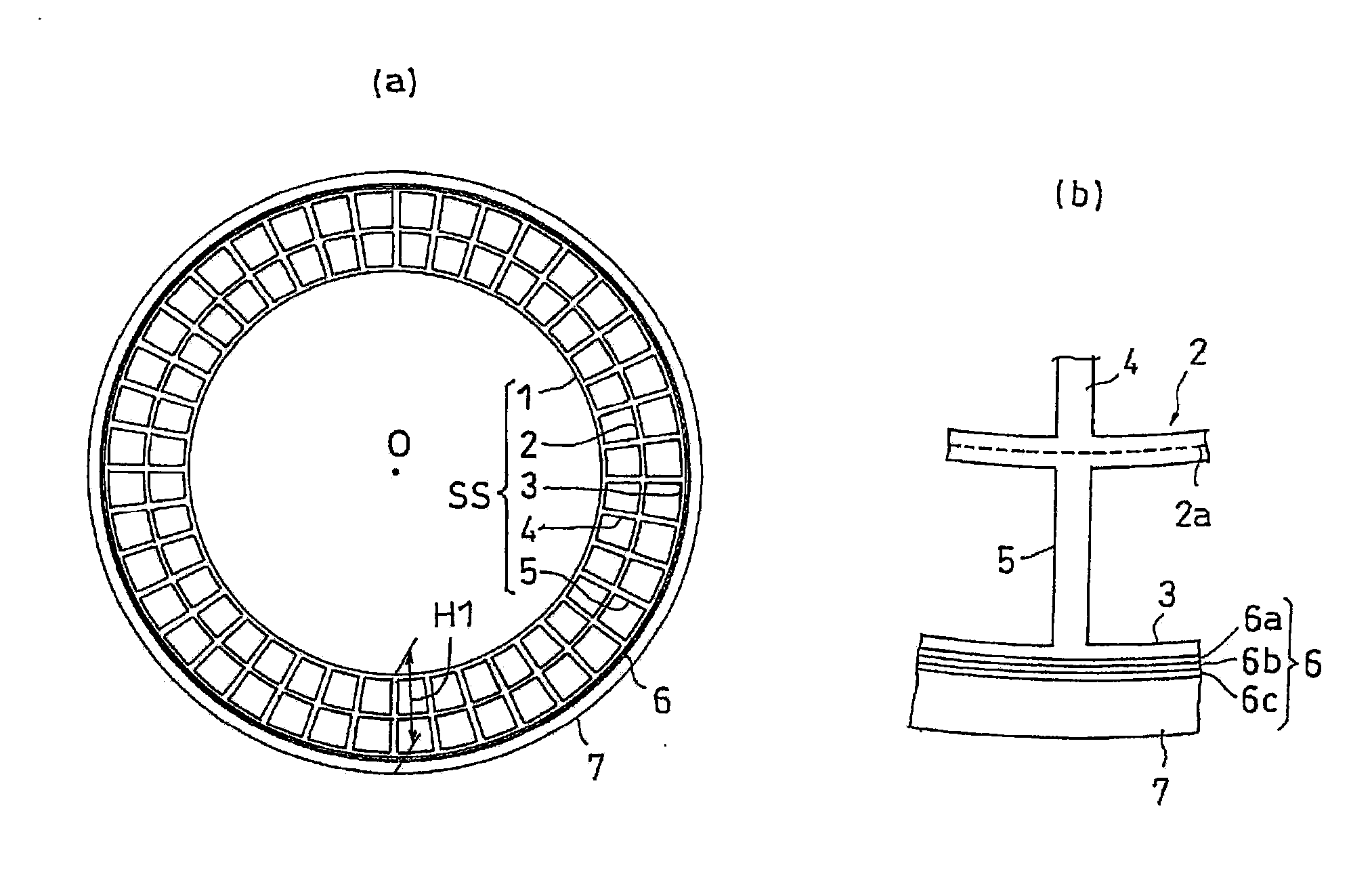
In a non-pneumatic tire having a support structure body supporting a load from a vehicle, the support structure body (SS) comprises an inner annular portion (1) an intermediate annular portion (2) provided concentrically in an outer side of the inner annular portion (1), an outer annular portion (3) provided concentrically in an outer side of the intermediate annular portion (2), a plurality of inner coupling portions (4) coupling the inner annular portion (1) and the intermediate annular portion (2) and being independent in a circumferential direction, and a plurality of outer coupling portions (5) coupling the outer annular portion (3) and the intermediate annular portion (2) and being independent in a circumferential direction.

Description

BACKGROUND OF THE INVENTION[0001]1. Field of the Invention[0002]The present invention relates to a non-pneumatic tire provided with a support structure body supporting a load from a vehicle, serving as a tire structure member, and preferably relates to a non-pneumatic tire which can be used in place of a pneumatic tire.[0003]2. Description of the Related Art[0004]A pneumatic tire has a function of supporting a load, a performance of absorbing a shock from a ground surface, and a performance of transmitting a power (accelerating, stopping and direction changing performance), and is accordingly employed in various vehicles, particularly a bicycle, a motor cycle, an automobile and a truck.[0005]Particularly, these capabilities greatly have contributed to a development of the automobile and other motor vehicles. Further, the shock absorbing performance of the pneumatic tire is useful in a transportation cart for medical equipment and an electronic device, and for other intended uses.[00...

Claims


Application Information

Patent Timeline
IPC IPC(8): B60C7/00B29D30/02
CPCB29D30/00B60C7/10B60C17/061B60C7/22B60C2007/107B60C7/18B60C7/107B60C7/101
Inventor IWASE, MASANORISEGAWA, MASAHIRO
Owner TOYO TIRE & RUBBER CO LTD
Learn More