Method of fabricating turbine airfoils and tip structures therefor

Inactive Publication Date: 2010-08-12
GENERAL ELECTRIC CO
View PDF21 Cites 94 Cited by
  • Summary
  • Abstract
  • Description
  • Claims
  • Application Information

AI Technical Summary

Benefits of technology

[0006]These and other shortcomings of the prior art are addressed by the present invention, which provides a method for supporting an airfoil core during casting, and for forming a tip structure on an airfoil while maintaining the metallurgical integrity of the finished component.
[0007]According to an aspect of the invention, a method for making a turbine airfoil tip structure includes: (a) providing a turbine airfoil having an outer wall which defines a hollow interior, wherein a tip of the airfoil is open to the hollow interior; (b) packing the interior of the airfoil with metallic powder; and (c)using laser energy, sintering an exposed layer of the powder so as to form a tip cap which is metallurgically bonded to the outer wall.
[0008]According to another aspect of the invention, a method for making a turbine airfoil includes: (a) providing a mold having: (i) a core; and (ii) an outer shell surrounding the core such that the core and the outer shell cooperatively define a cavity in the shape of a hollow airfoil having an outer wall, a root, and a tip; (iii) wherein at least a tip portion of the core extends completely through the portion of the cavity defining the tip of the airfoil; (b) restraining the tip portion of the core so as to prevent relative movement between the core and the outer shell; (c) introducing molten metal alloy into the

Problems solved by technology

Cast turbine airfoils for advanced gas turbine engines have internal features that challenge the capability of current casting technologies.
The castings require complex ceramic cores to form the internal features and these cores are fragile during the casting process.
The issue is compounded by exotic alloys such as single crystal materials that drive up the cost to cast a part and thus drive up the cost caused by scrapping hardware.
One basic casting limitation is that the ceramic core that forms the internal structure of the airfoil can only be secured by the lower (i.e. root) portion with the majority of t

Method used


Image

  • Method of fabricating turbine airfoils and tip structures therefor
  • Method of fabricating turbine airfoils and tip structures therefor
  • Method of fabricating turbine airfoils and tip structures therefor

Examples


Embodiment Construction

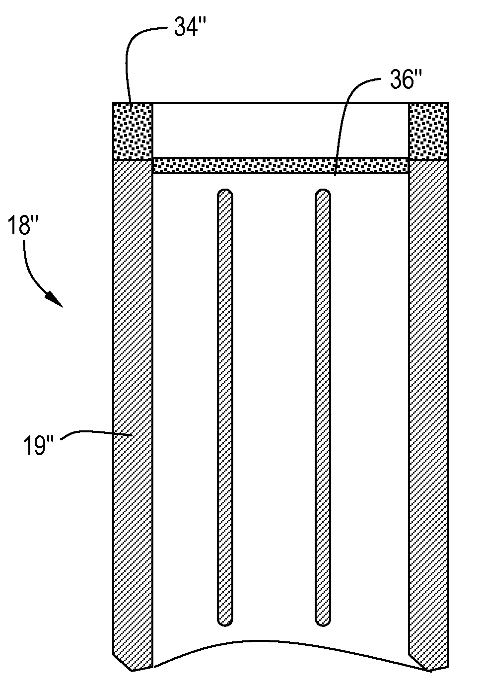
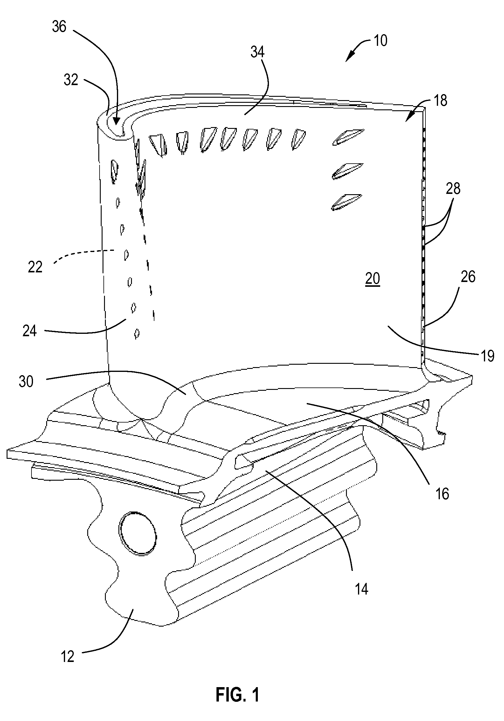
[0028]Referring to the drawings wherein identical reference numerals denote the same elements throughout the various views, FIG. 1 illustrates an exemplary turbine blade 10. The turbine blade 10 includes a conventional dovetail 12, which may have any suitable form including tangs that engage complementary tangs of a dovetail slot in a rotor disk (not shown) for radially retaining the blade 10 to the disk as it rotates during operation. A blade shank 14 extends radially upwardly from the dovetail 12 and terminates in a platform 16 that projects laterally outwardly from and surrounds the shank 14. A hollow airfoil 18 extends radially outwardly from the platform 16. The airfoil 18 has an outer wall 19 comprising concave pressure side outer wall 20 and a convex suction side outer wall 22 joined together at a leading edge 24 and at a trailing edge 26. The trailing edge 26 may incorporate trailing edge cooling passages such as the illustrated holes 28. The airfoil 18 has a root 30 and a t...


PUM

PropertyMeasurementUnit
Thicknessaaaaaaaaaa
Lengthaaaaaaaaaa
Pressureaaaaaaaaaa

Abstract

A method for making a turbine airfoil includes providing a mold core and an outer shell which cooperatively define a cavity in the shape of a hollow airfoil having an outer wall, a root, and a tip. A tip portion of the core extends completely through the portion of the cavity defining the tip of the airfoil. The core is restrained to prevent movement between the core and outer shell. Molten metal is introduced into the cavity and solidified to form an airfoil having at least one outer wall which defines an open tip and a hollow interior. A metallic tip cap is formed on the outer wall which substantially closes off the open tip. The tip cap may be formed by packing the airfoil with metallic powder; and laser sintering the exposed powder so as to form a tip cap which is metallurgically bonded to the outer wall.

Description

BACKGROUND OF THE INVENTION[0001]This invention relates generally to the manufacture and repair of gas turbine engine components and more particularly to the production of tip cap structures for turbine airfoils.[0002]Cast turbine airfoils for advanced gas turbine engines have internal features that challenge the capability of current casting technologies. The castings require complex ceramic cores to form the internal features and these cores are fragile during the casting process. The result is that casting yields of 50 percent to 70 percent are not uncommon. The 30 percent to 50 percent casting scrap factors into the cost of the useable castings.[0003]The issue is compounded by exotic alloys such as single crystal materials that drive up the cost to cast a part and thus drive up the cost caused by scrapping hardware. If a mere 5 percent to 10 percent casting yield improvement can be achieved, the impact to each gas turbine engine is in the millions of dollars per year, based on v...

Claims


Application Information

Patent Timeline
IPC IPC(8): B22D27/02B22F7/04B22D29/00B23P6/00
CPCB22F3/105B22F5/04B22F7/06B23K26/03B23K26/063B23K26/34Y10T29/49318B23K2201/001B23P6/007B23K26/3213B23K26/3273B23K26/345B23K35/0244B23K26/421B23K26/32B23K26/342B23K26/0622B23K26/60B23K2101/001B23K2103/08B23K2103/18B23K2103/26
Inventor QI, HUANAZER, MAGDISINGH, PRABHJOTROCKSTROH, TODD JAYTEWARI, SUDHIR K.SABATO, JOSEPH GIANCARLODESANDER, DONALD BRETTGLEDHILL, MARK DOUGLAS
Owner GENERAL ELECTRIC CO
Why Eureka
Try Eureka