
Vertical system for the plating treatment of a work piece and method for conveying the work piece

a technology of work piece and vertical system, which is applied in the direction of printed circuit board manufacturer, electronic components, tanks, etc., can solve the problems of insufficient uniformity of metal layer deposited, no longer possible to realise such precision structures, and new challenges for printed circuit board manufacturer with chip-carrier

Active Publication Date: 2010-08-12
ATOTECH DEUT GMBH
View PDF10 Cites 14 Cited by
  • Summary
  • Abstract
  • Description
  • Claims
  • Application Information

AI Technical Summary

Benefits of technology

The present invention aims to improve existing apparatuses to avoid their disadvantages and achieve a reproducible treatment of work pieces, especially for forming metal structures on their surfaces. It also enables treatment of foil-like work pieces and ensures high cleanliness and long service life of the treatment baths. The invention aims to produce work pieces cost-effectively and treat them optimally, creating the best treatment conditions for each position and step. It also aims to create treatment conditions that are reproducible and minimize variations in dimensions and time. The invention provides flexibility in the sequence of treatment steps, adjustability of treatment parameters, and adaptability of system size, while documenting individual treatment conditions for each work piece.

Problems solved by technology

However, these dimensions too are only intermediate steps on the road to even smaller structures.
Based on the advancing miniaturisation of semiconductor components, new challenges are arising for the manufacturers of printed circuit boards with chip-carriers to adapt their products to new conditions.
It is no longer possible to realise such precision structures with the necessary quality using today's conventional methods and apparatuses in printed circuit board production.
In addition, it has also been established that the uniformity of the metal layers deposited is insufficient.
This is not acceptable as the electric characteristics of the circuits produced in this way will be impaired in an unforeseeable manner, which means that the circuits will have to be rejected.
The known apparatuses have the disadvantage that the work pieces are not treated precisely enough to be able to produce metal structures again and again in the aforementioned structural sizes.

Method used


Image

  • Vertical system for the plating treatment of a work piece and method for conveying the work piece
  • Vertical system for the plating treatment of a work piece and method for conveying the work piece
  • Vertical system for the plating treatment of a work piece and method for conveying the work piece

Examples


Embodiment Construction

[0018]These objects are achieved through the system for the plating treatment of a work piece in accordance with claim 1 and through the method for conveying a work piece retained in vertical orientation in accordance with claim 27. Preferred specific embodiments of the invention are specified in the sub claims.

[0019]As far as the term “vertical system” is used in the description below and in the claims, this refers to a treatment system in which work pieces are able to be treated, the said work pieces being substantially in vertical orientation both during the treatment and during transport from one treatment module to another (i.e., in an orientation in which the work pieces are inclined by a maximum of 20° each relative to the perpendicular).

[0020]As far as the term “plating treatment” is used in the description below and in the claims, this refers to a treatment where work pieces are treated by means of liquid or gaseous treatment agents, the work pieces more especially in a pro...


PUM

PropertyMeasurementUnit
clamping forceaaaaaaaaaa
tension forcesaaaaaaaaaa
anglesaaaaaaaaaa

Abstract

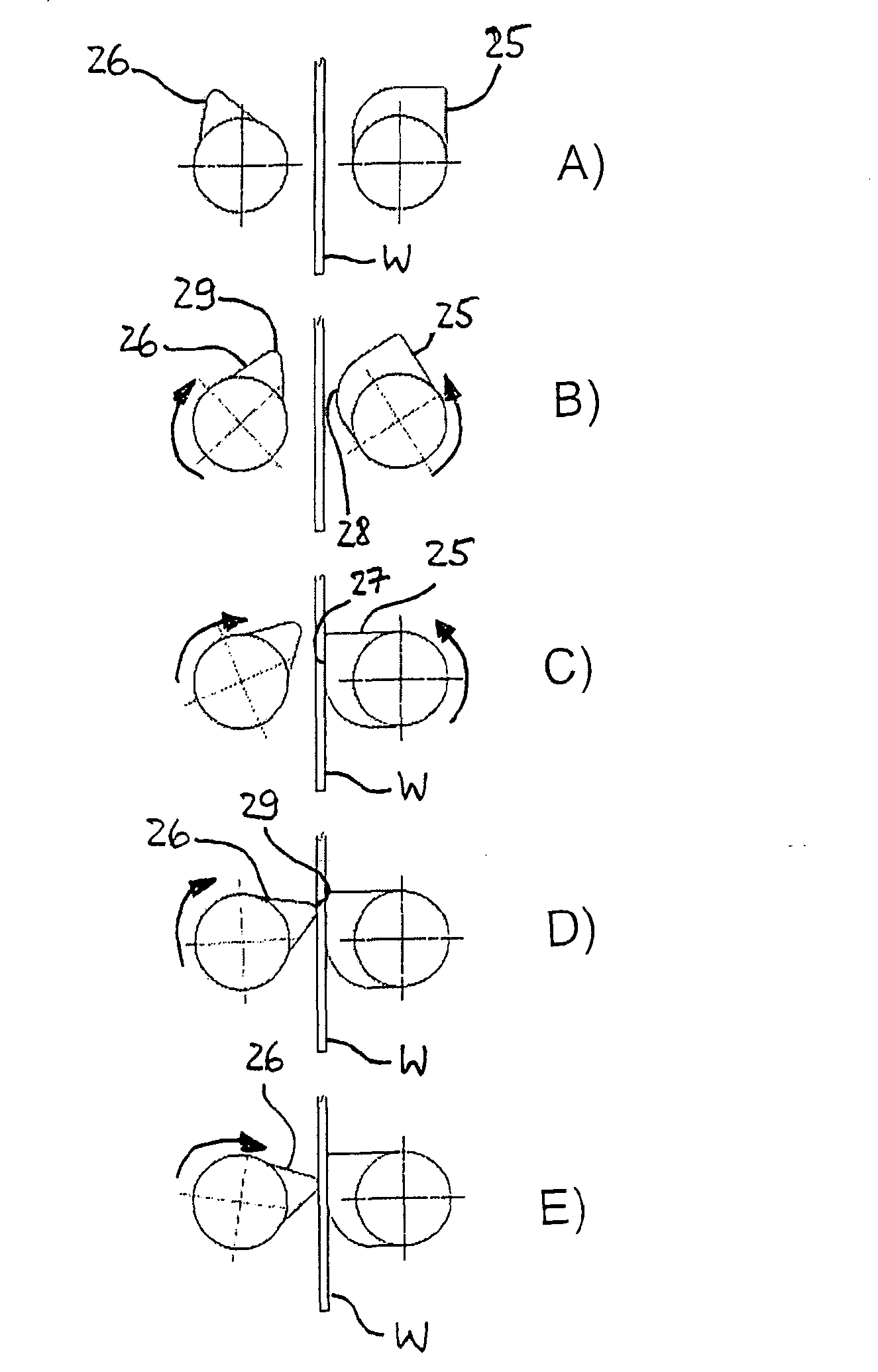
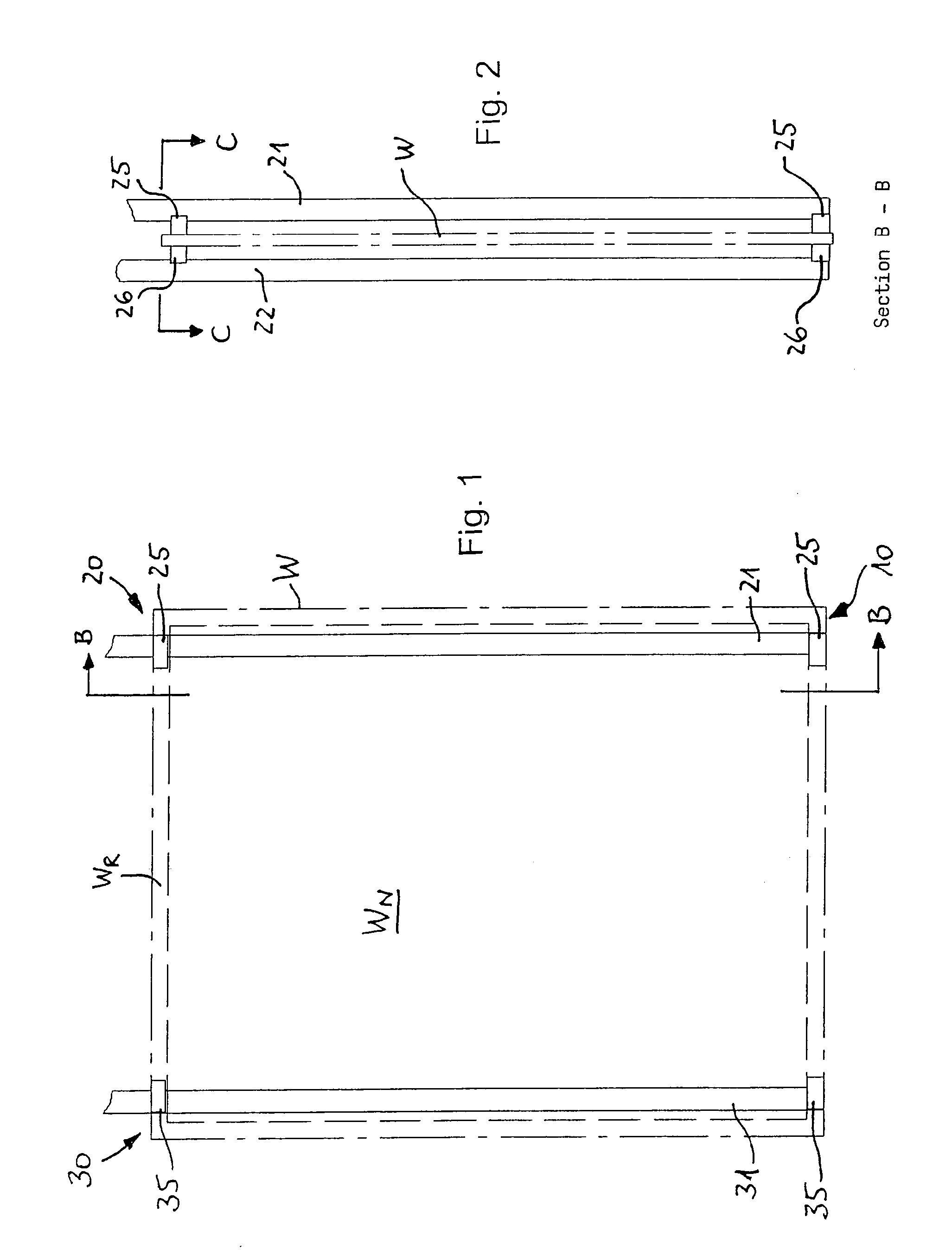
The present invention relates to a vertical system for the plating treatment of a work piece (W), the said system including at least two treatment modules (100) and at least one transport device for conveying at least one work piece (W) to a treatment module (100) and for transferring the work piece (W) to retaining devices (130) in the treatment module (100). The retaining devices (130) for the work piece (W) are provided in the treatment modules (100). The transport device includes at least one gripping device (10) retaining the work piece (W) each with at least one fastening device (20, 30). Each fastening device (20, 30) includes first clamping devices (25, 35) that are each associated with one side of the work piece (W) and second clamping devices (26). At least one first clamping device (25, 35) associated with a first side of the work piece (W) is designed and disposed such that the position of the first side of the work piece (W) can be defined by the first clamping device (25, 35). At least one second clamping device (26) associated with a second side of the work piece (W) is designed and disposed such that a clamping force can be exerted onto the work piece (W) by the said clamping device. Both the first clamping device (25, 35) and the second clamping device (26) are moveable. According to the invention, the gripping device (10) is actuated as follows: a) moving the first clamping device (25, 35) such that the first clamping device (25, 35) takes over a contact position and thereby the position of the first side of the work piece (W) is defined, and b) moving the second clamping device (26) such that the second clamping device (26) takes over a clamping position and the work piece (W) is thereby clamped together with the at least one first clamping device (25, 35). In doing so the first clamping device (25, 35) takes over the contact position before the second clamping device (26) takes the clamping position.

Description

FIELD OF THE INVENTION[0001]The present invention relates to a vertical system for the plating treatment of work pieces and to a method for conveying work pieces that are retained in vertical orientation by a gripping device to a treatment module.[0002]Plating systems are used, i.a., for the treatment of printed circuit boards and printed circuit foils and semiconductor wafers as well as in the production of photoelectric cells, such as photoelectric solar cells, and of monitor plates. The treatment in these systems typically comprises chemical and electrochemical treatment methods.BACKGROUND ART[0003]At the moment chip producers in the semiconductor industry are working on the introduction of so-called 65-nanometer structures (Computertechnik (10), 2007). Even smaller structures of 45 nm are in the process of being developed. However, these dimensions too are only intermediate steps on the road to even smaller structures. Based on the advancing miniaturisation of semiconductor comp...

Claims


Application Information

Patent Timeline
Patent Type & Authority Applications(United States)
IPC IPC(8): C25D5/00C25D17/00
CPCC25D17/00H05K3/241C25D17/06C25D7/123C25D17/001C25D17/02C25D17/04
Inventor SCHNEIDER, REINHARDHAUF, UWESCHELLER, BRITTAKUNZE, HENRYWIENER, FERDINANDKLINGL, HEINZ
Owner ATOTECH DEUT GMBH
Learn More