Capacitive proximity tactile sensor

a tactile sensor and capacitive technology, applied in the field of capacitive proximity sensors, can solve the problems of inaccurate scale performance, inability to effectively measure the progressive force applied by the object onto the surface of the sensor, and the proximity effect does not measure the pressure or the force applied by the object, etc., to achieve uniform sensitivity and improve the effect of simple manufacturing process

Active Publication Date: 2010-08-12
PRESSURE PROFILE SYST
View PDF17 Cites 62 Cited by
  • Summary
  • Abstract
  • Description
  • Claims
  • Application Information

AI Technical Summary

Benefits of technology

[0009]It is a further object of the present invention to provide a capacitance proximity tactile sensor which is amenable for simple manufacturing process.
[0010]It is a yet another object of the present invention to provide a capacitance proximity tactile sensor with uniform sensitivity.
[0011]It is yet another object of the present invention to provide a capacitance tactile sensor that is flexible and can be bent or folded around or onto a flat or curved surface.
[0012]The sensor of the invention includes a capacitive sensing electrode layer and a compressible non-conductive layer. When a conductive object is placed nearby, a proximity sensor is formed between the capacitive sensing electrode and the conductive object allowing dete...

Problems solved by technology

While the sensitivity of such capacitive touch sensors is very high in detecting the presence or absence of a conductive object nearby, they cannot be used effectively to measure the progressive force applied by the object onto the surface of the sensor.
However, this proximity effect does not measure the pressure or the force applied by the object such as the foot.
Instead, by integrating all the measurements it effectively provides the foot size rather than the person's weight—studies of scale performance ha...

Method used


Image

  • Capacitive proximity tactile sensor
  • Capacitive proximity tactile sensor
  • Capacitive proximity tactile sensor

Examples


Embodiment Construction

[0023]A detailed description of the present invention follows with reference to accompanying drawings in which like elements are indicated by like reference letters and numerals.

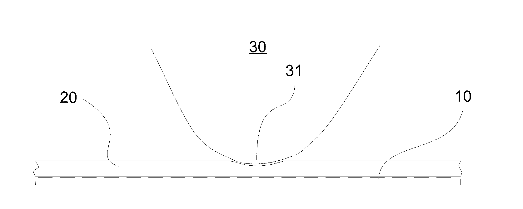
[0024]FIG. 3 depicts the general illustration of the sensor of the present invention which includes two main elements—At least one capacitive sensing electrode layer 10 and a compressible non-conductive layer 20. The capacitive sensing electrode layer 10 is formed in a manner similar to that of traditional proximity sensor arrays. It contains a number of locations (pixels) capable of measuring electrical and capacitive characteristics when a conductive object 30 is positioned nearby. Specific number of pixels and their design depend highly on a particular application; some examples of those are described in more detail below. Signals from individual pixels are transmitted via a cable (not shown) to a control unit (not shown). In some applications, the control unit is incorporated within the sensor device its...


PUM


Abstract

A novel capacitive proximity tactile sensor is formed by an electrode layer and a compressible non-conductive layer. Positioning a conductive object in contact with the sensor and applying contact force onto the sensor surface allows for both detecting the location of touch (as in traditional proximity sensors) as well as measuring contact force (as in tactile array sensors) due to a capacitance-measuring sensor formed between the electrode layer and the object with the compressible non-conductive layer therebetween. Useful applications of the sensor include input device for consumer electronic item, flexible and thin weight scale, shoe insole for monitoring pressure distribution of a foot while walking, pressure-monitoring seat cushion and others.

Description

CROSS REFERENCE TO RELATED APPLICATIONS[0001]This application claims a priority benefit from a U.S. provisional patent application No. 61 / 150,580 by the same inventor, which was filed Feb. 6, 2009 with the same title. This application is expressly incorporated herein in its entirety by reference.BACKGROUND OF THE INVENTION[0002]The present invention relates generally to capacitive proximity sensors. More particularly, the sensor of the invention utilizes a proximity array sensor covered with a layer of compressible non-conducting material allowing it to detect both the presence of a conductive object nearby and the force applied by such object onto the sensor surface.[0003]Capacitive touch sensors are commonly used as an input device in consumer electronics. iPhone by Apple, Inc. for example is a widely-used device with an improved user interface made possible by using a proximity touch sensor input device. While the sensitivity of such capacitive touch sensors is very high in detec...

Claims


Application Information

Patent Timeline
IPC IPC(8): G06F3/045G06F3/044
CPCG06F3/044G06F3/0447
Inventor SON, JAE S.
Owner PRESSURE PROFILE SYST
Why Eureka
Try Eureka