Non-invasive injection of light into a transparent substrate, such as a window pane through its face

a transparent substrate and non-invasive technology, applied in the field of illumination of transparent substances, can solve the problem of inability to achieve the range of angles

Inactive Publication Date: 2010-08-12
LUMINATED GLAZINGS LLC
View PDF30 Cites 72 Cited by
  • Summary
  • Abstract
  • Description
  • Claims
  • Application Information

AI Technical Summary

Benefits of technology

[0021]The LED surface temperature will present a thermal shock to the window and so the coupling method between the LED and the window should introduce a sufficient thermal break to avoid window damage. One such method may be the use of a thick layer of high temperature coupling grease, keeping in mind any modified ray distributions from the LED when passing through the grease, such as that due to bubbles in the grease and the expanded area of the grease compared to the LED. Another may be to interpose a layer of shock-resistant glass (e.g., borosilicate) whose optical properties are consistent with the application (e.g., wavelength transmittance, low haze, etc.). In both instances, the heat from the LED is preferentially conducted away from the window (to a thermally bonded heatsink), thereby lowering the surface temperature of the LED and minimizing the thermal shock to the window, especially important when the window has thermally stabilized at a low temperature (e.g., uninsulated window pane during a cold winter day) where a thermal shock (from the concentrated heat load of the LED) might cause the window to crack.
[0026]The LEDs can be flashed on-and-off in order to act, in part or in full, as a communication medium via extraction patterns on the window. For example, in a mall-setting, one store's window can communicate with another's, thereby providing wireless links to coordinate special effects, further enhancing the retrofit opportunities. As is well known in the art, the LEDs can be flashed at high frequencies unperceivable by the human eye.
[0029]Commercially available acrylic sheets (e.g., CYRO Industries' ACRYLITE EndLighten, Altuglas' Elit II, and Lucite International's Perspex Prismex) that are designed to be edge-lighted from a fluorescent lamp, and are known to already have small extraction features precisely distributed across their surface(s) (e.g., via an array of printed dots on their surface; see, e.g., U.S. Pat. No. 4,937,709, filed August-1989) provide uniform illumination. Such a dot pattern may be optimized for use with the instant invention. In fact, there are large-bed inkjet printers that can dispense white ink (http: / / www.rdga.com / color / products / inks / White / ) and it is contemplated that other materials (e.g., micron-sized glass beads and / or fluorescent inks in a UV curable adhesive that matches the refractive index of the window) can be dispensed, silk-screened, etc., and that would cause light to exit the window in a predetermined pattern.
[0031]The LED power source may be located a distance from the LED. It has been found that microphone cable (manufactured by Mogami, available from www.redco.com) provides excellent flexibility and can handle the typical current (e.g., 700 mA) of a string of high brightness LEDs. Should the LED be placed towards the center of a window, it may be desirable to use very thin wires (LEDs typically require 700 milliamps or less) or transparent conductors (e.g., vacuum deposited layer of Indium Tin Oxide (ITO) on optically clear film: http: / / www.sheldahl.com / Product / TMAccentia.htm) to carry the current to the LED without being obtrusive.
[0035]Various types of coupling media for filling any gap between the optic that delivers light to the substrate and the substrate have been successfully utilized, including tap water, hair-gel, food-grade grease, Vaseline petroleum jelly, double-stick tape, acrylic based sealant, mineral oil and microscope coupling fluid. Some coupling media, like 3M Scotch-brand double stick tape, can also support the weight of the LED / heatsink assembly. Greases and sealants are especially useful when used with glass clamps as they do not run-off like mineral oil and tap water. The key aspects of this media are its refractive index and its clarity. The index must be high enough so that light can exit the optic and enter the window at the appropriate angles. High clarity ensures high coupling efficiency. Note that other properties of the media also should be considered, such as thickness (vis-à-vis clarity and its effect on the path of light rays), thermal insulation, compliance to accommodate mismatches between the coefficient of thermal expansion between the optic and the window or substrate, adhesion over environmental conditions, ease of removal during servicing or repositioning, and stability under prolonged exposure from ultraviolet light (either from the LED or sunlight). Further, the overall design approach should avoid contributing to excessive stress or strain on the window pane to minimize the risk of breakage (during normal operation, and considering, for example, someone pulling on the device after it is optically coupled to the window).

Problems solved by technology

However, as stated previously, this range of angles is not possible for that shown in FIG. 5.
Finally, note that non-imaging optics (when used with a multi-lumen LED) would have a length that may interfere with existing structures in retrofit applications, and might require additional spacing between adjacent mall glass windows in new installations (or require wider window frames for a given size exterior window).

Method used


Image

  • Non-invasive injection of light into a transparent substrate, such as a window pane through its face
  • Non-invasive injection of light into a transparent substrate, such as a window pane through its face
  • Non-invasive injection of light into a transparent substrate, such as a window pane through its face

Examples


Embodiment Construction

[0018]The following is a description of some embodiments. It is not intended to limit the scope hereof, as other embodiments and arrangements may also achieve the same objective and operate and perform in a similar manner.

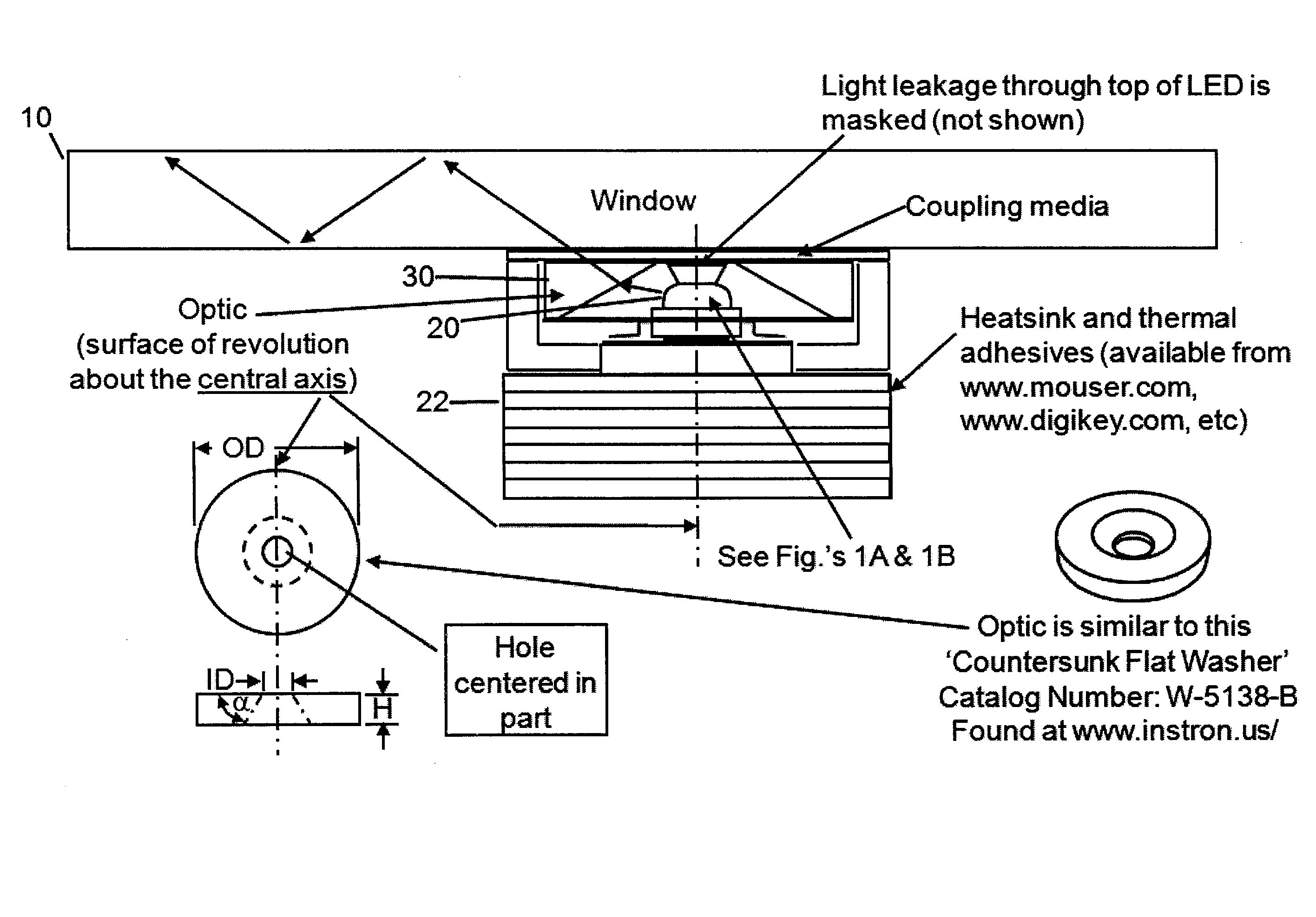
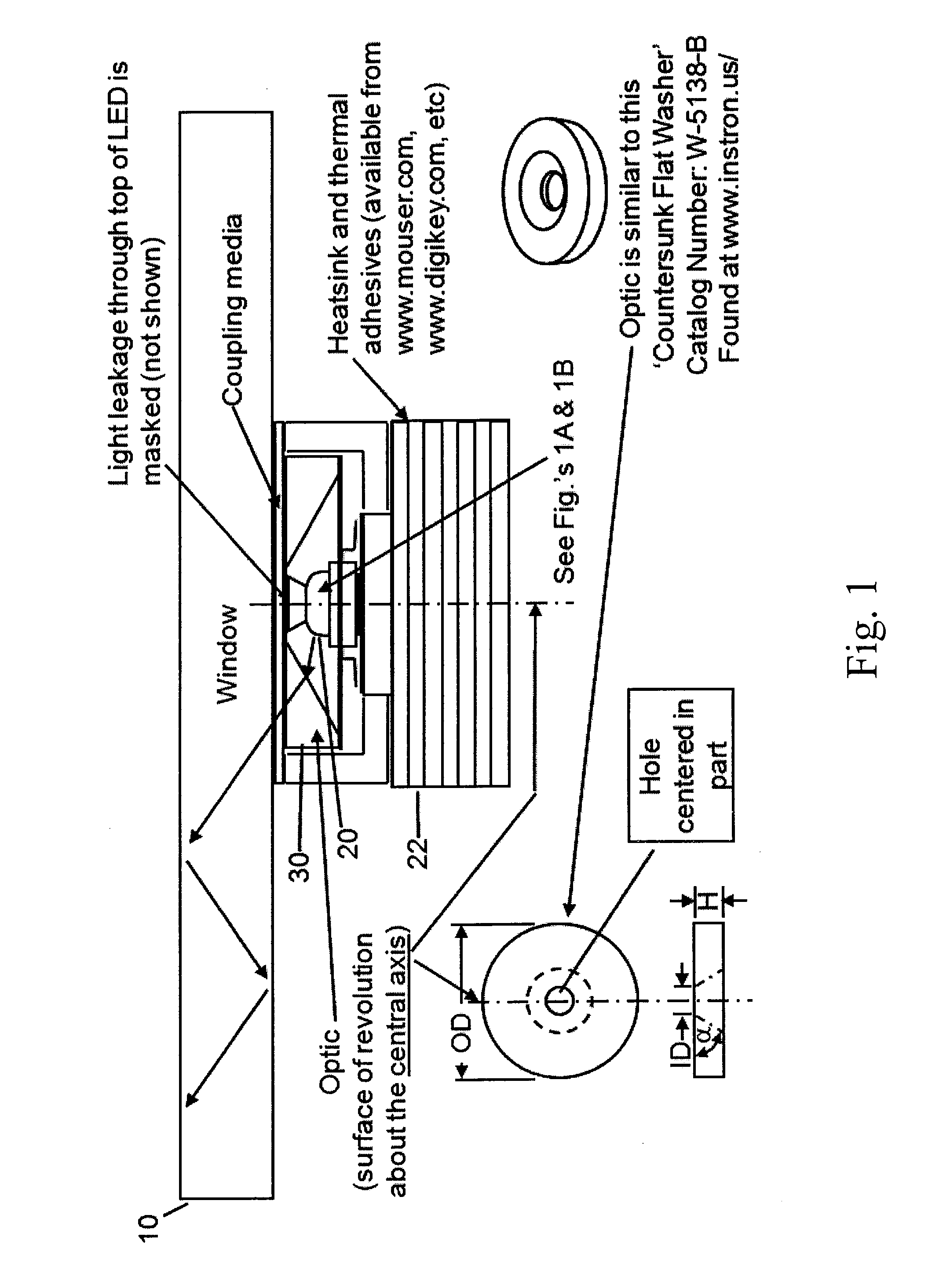
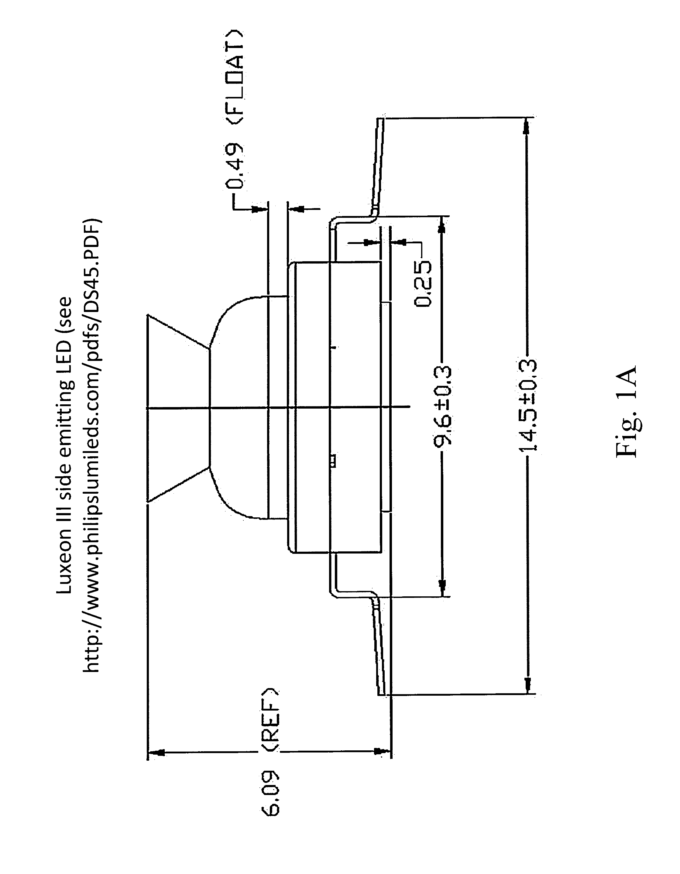
[0019]As shown in FIGS. 1 and 7, a side-emitting light emitting diode (see e.g., U.S. Pat. No. 6,598,998, filed May 2001, and commercially available e.g., Lumileds P / N LXHL-DW03, http: / / www.luxeonstar.com / ) is fitted with a special optic which is in the general shape of a thick countersunk flat washer made from clear acrylic or polycarbonate. That assembly is affixed to the face (not to an edge) of a window pane, e.g., via double stick tape such as 3M Scotch brand clear mounting tape, P / N 4010T. This arrangement, which is known as ‘prism-coupling’, (see, e.g., U.S. Pat. No. 4,545,642) forces light to travel within the window pane as if it were a light guide. Light is thereby trapped within the window pane via total internal reflection. This allows light to be coupl...


PUM


Abstract

Apparatus for illuminating a feature on a transparent light transmitting substrate or window: the substrate is capable of trapping light within itself and propagating the light along the substrate with total internal reflection. A light source is connected by an optical arrangement positioned with respect to one of the surfaces of the substrate for directing light into the substrate at an incident angle selected for propagation of light along the substrate. An extraction feature at a location on the surface of the substrate is configured to illuminate internal reflection at the feature, so that the feature becomes illuminated. Arrangements for the shape, orientation and adjustment of the optic, for configurations of the feature, for coupling the optic and also for coupling the feature to the substrate and particularly its surface are disclosed.

Description

CROSS REFERENCE TO RELATED APPLICATION[0001]This application claims the benefit of U.S. Provisional Application No. 61 / 201,524, filed on Dec. 11, 2008, incorporated herein by reference.BACKGROUND OF THE INVENTION[0002]1. Field of the Invention[0003]This invention concerns illuminating a transparent substance, such as existing storefront window pane and particularly storefront panes. It is desirable to illuminate in a cost-effective manner so as to attract attention and try to promote incremental sales.[0004]Light (UV, visible and / or IR) from a source (e.g., LED, laser diode, optical fiber, fluorescent or photoluminescent materials) is optically coupled into a transparent substrate (e.g., storefront window) via toroidal or circular (FIGS. 1, 2, 4, 12) prism couplers. These couplers can be refractive (FIG. 1), reflective (FIG. 4), or some combination thereof, and comprise a refractive medium (e.g. oil, gel, water, adhesive, etc) between the optic (e.g. circular prism) and the substrat...

Claims


Application Information

Patent Timeline
Patent Type & Authority Applications(United States)
IPC IPC(8): F21V9/16F21V3/04F21V7/09F21S8/00F21V5/00F21V7/00F21V17/02
CPCF21V3/04F21V13/04G09F13/04F21V9/16G02B6/0025G02B6/0031G02B6/0036G02B6/0051G02B6/0085G02B6/0095
Inventor SACCOMANNO, ROBERT
Owner LUMINATED GLAZINGS LLC
Why Eureka
Try Eureka