Dynamic Queue Memory Allocation With Flow Control

a flow control and queue technology, applied in the field of ethernet controllers, can solve the problems of data frame dumping, data transfer disruption, network traffic flow not always consistent, etc., and achieve the effect of low memory usage and high memory usag

Inactive Publication Date: 2010-08-12
MICREL
View PDF4 Cites 14 Cited by
  • Summary
  • Abstract
  • Description
  • Claims
  • Application Information

AI Technical Summary

Benefits of technology

[0006]According to one embodiment of the present invention, a method in an Ethernet controller for allocating memory space in a buffer memory between a transmit queue (TXQ) and a receive queue (RXQ) includes allocating initial memory space in the buffer memory to the RXQ and the TXQ; defining a RXQ high watermark indicating high memory usage in the RXQ and a RXQ low watermark indicating low memory usage in the RXQ; receiving an ingress data frame; determining if a memory usage in the RXQ exceeds the RXQ high watermark; if the memory usage in the RXQ does not exceed the RXQ high watermark, storing the ingress data frame in the RXQ; if the memory usage in the RXQ is at or exceed the RXQ high watermark, determining if there are unused memory space in the TXQ; if there are no unused memory space in the TXQ, transmitting a pause frame to halt further ingress data frame; if there are unused memory space in the TXQ, allocating unused memory space in the TXQ to the RXQ; and storing the ingress data frame in the RXQ.

Problems solved by technology

The flow of network traffic to and from the Ethernet controller is not always consistent or even.
The more handshakes between link partners for buffer status update, the more disruption is created in the regular data transfer.
In extreme case, the deluge of ingress frames filling up the RXQ buffer will cause data frames to be discarded and requires retransmission of the dropped data frames.
The Pause frames, the additional handshakes for buffer status update, and the retransmission of dropped frames all have a negative impact on the network bandwidth usage and the overall system throughput and performance are consequently degraded.

Method used


Image

  • Dynamic Queue Memory Allocation With Flow Control
  • Dynamic Queue Memory Allocation With Flow Control
  • Dynamic Queue Memory Allocation With Flow Control

Examples


Embodiment Construction

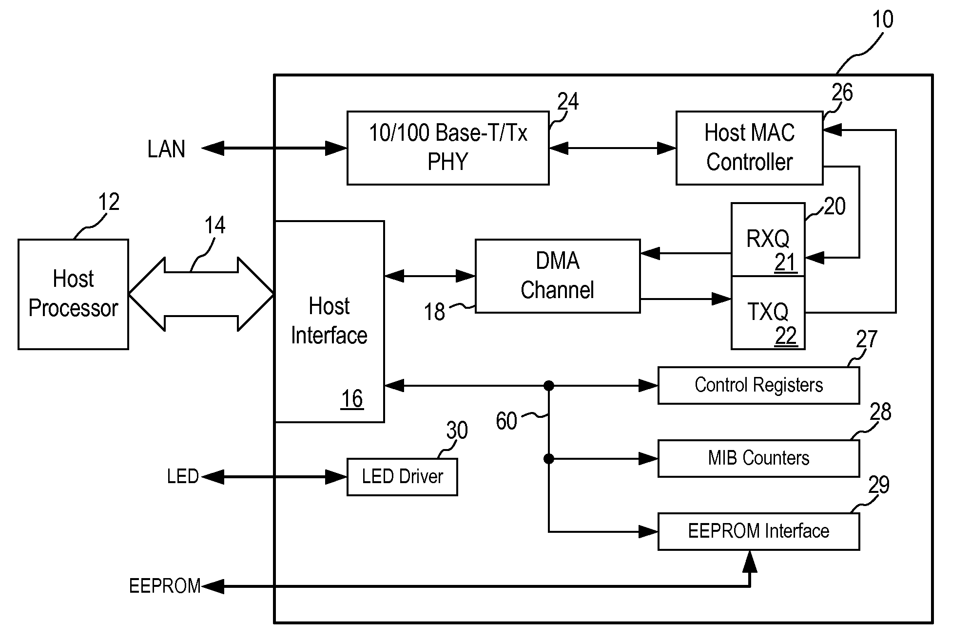
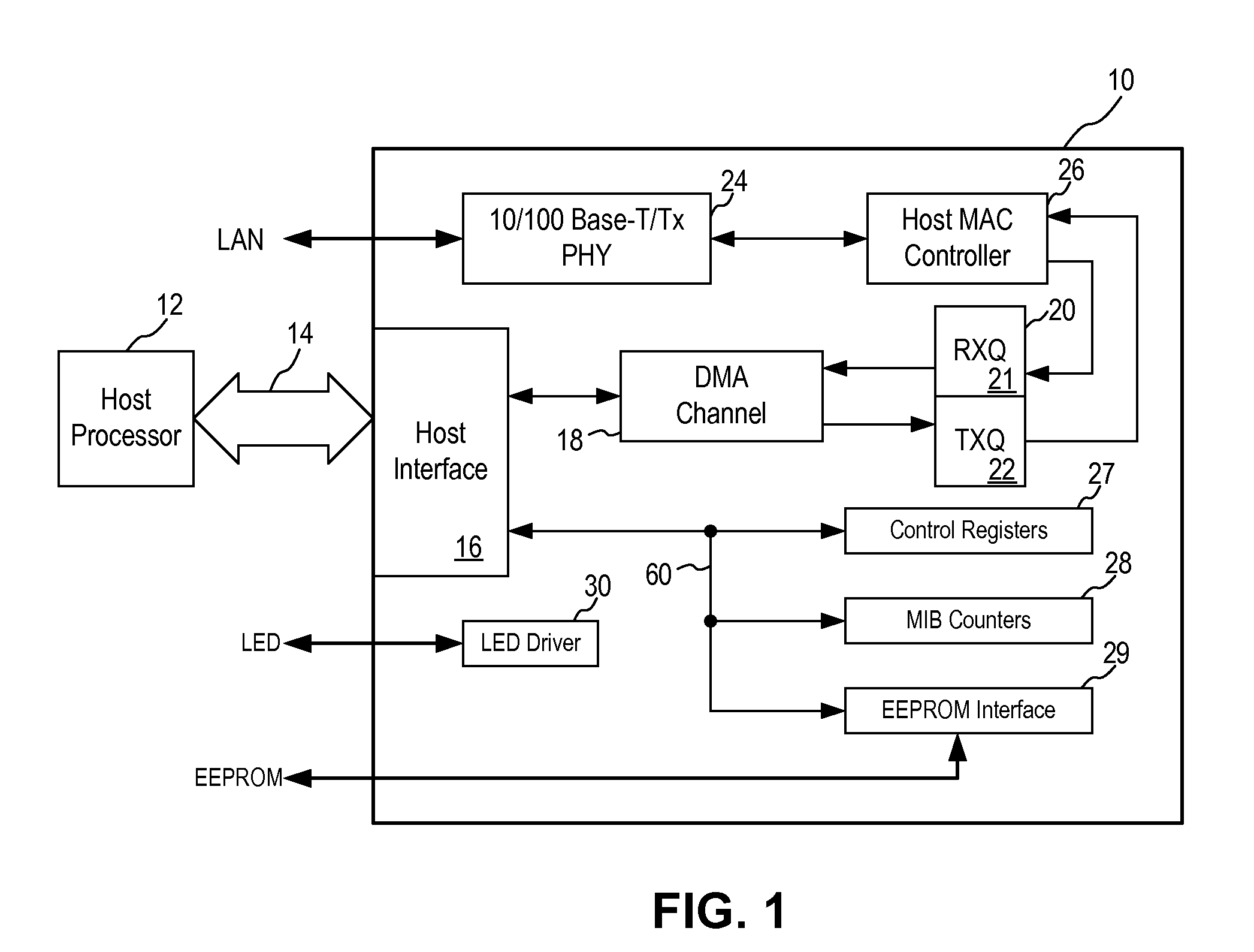
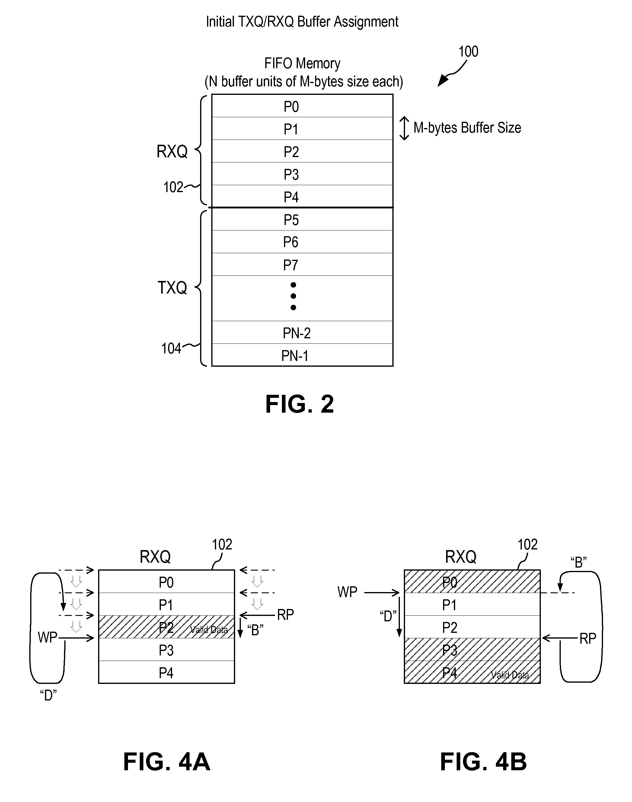
[0019]In accordance with the principles of the present invention, a dynamic queue memory allocation method is implemented in an Ethernet controller to allow the total queue memory space to be shared intelligently between the receive queue (RXQ) and the transmit queue (TXQ). The available memory space in the queue memory is dynamically allocated based on network traffic to allow either more ingress frames or more egress frames to be stored. When the additional memory space is no longer required, the dynamically allocated space is returned to the respective memory queue to ensure efficient usage of memory space.

[0020]In one embodiment, unused transmit queue (TXQ) buffers are “borrowed” or allocated to the receive queue (RXQ) to allow more ingress data frames to be received. With unused TXQ buffers available for borrowing, the receive logic, such as the Queue Management Unit, monitors the RXQ free space and borrows buffer space from TXQ to reduce the need to send Pause frames or discar...


PUM


Abstract

A method in an Ethernet controller for allocating memory space in a buffer memory between a transmit queue (TXQ) and a receive queue (RXQ) includes allocating initial memory space in the buffer memory to the RXQ and the TXQ; defining a RXQ high watermark and a RXQ low watermark; receiving an ingress data frame; determining if a memory usage in the RXQ exceeds the RXQ high watermark; if the RXQ high watermark is not exceeded, storing the ingress data frame in the RXQ; if the RXQ high watermark is exceeded, determining if there are unused memory space in the TXQ; if there are no unused memory space in the TXQ, transmitting a pause frame to halt further ingress data frame; if there are unused memory space in the TXQ, allocating unused memory space in the TXQ to the RXQ; and storing the ingress data frame in the RXQ.

Description

FIELD OF THE INVENTION[0001]The invention relates to Ethernet controllers and, in particular, to an Ethernet controller implementing dynamic queue memory allocation.DESCRIPTION OF THE RELATED ART[0002]Ethernet Controllers are incorporated in networking devices to provide network communication functions. For example, cable or satellite set-top boxes or voice over IP adapters incorporate Ethernet controllers for communicating with a data network, such as a local area network (LAN) implemented under the IEEE 802.3 standards. A conventional Ethernet controller includes a buffer memory for storing the transmit and receive data. A Queue Management Unit (QMU) in the Ethernet controller manages packet traffic between the MAC / PHY interface and the host processor. In general, the buffer memory is implemented using a FIFO (first-in-first-out) memory and is divided into a receive queue (RXQ) and a transmit queue (TXQ). The buffer memory is therefore also referred to as the queue memory.[0003]In...

Claims


Application Information

Patent Timeline
Patent Type & Authority Applications(United States)
IPC IPC(8): H04L12/56
CPCH04L47/10H04L47/13H04L47/266H04L49/9078H04L49/90H04L49/901H04L47/29
Inventor LUAN, CHUNG CHEN
Owner MICREL
Why Eureka
Try Eureka