Transmission device

Active Publication Date: 2010-08-12
PANASONIC CORP
View PDF6 Cites 12 Cited by
  • Summary
  • Abstract
  • Description
  • Claims
  • Application Information

AI Technical Summary

Benefits of technology

[0012]With the above-described structure, the transmission device converts one of n data sequences into a converted data sequence by applying encoding processing so that a same value is continuous a predetermined number of times or less. The transmission device then inverts or non-inverts a specific data sequence according to a determination as to whether or not an updated cumulative value approaches a standard value. Since an n-bit symbol to be amplitude modulated includes a bit in the specific data sequence as a most significant bit and always includes abit in the converted data sequence

Problems solved by technology

However, when the above 8B/10B encoding system is used with multilevel modulation that has more than two modulation conditions, e.g. when using four-level modulation, then the run length and the DC balance are not guaranteed.
When the run length is not guaranteed, clock recovery in the reception circuit is not possible since a modulation change does not occur, and thus the problem occurs that demodulation in the reception device cannot be p

Method used


Image

  • Transmission device
  • Transmission device
  • Transmission device

Examples


embodiment 1

1. Embodiment 1

[0082]The following describes Embodiment 1 of the present invention with reference to the figures.

1.1. Outline of Transmission / Reception System 1

[0083]The following is an outline of the transmission / reception system 1, which includes a transmission device according to the present invention.

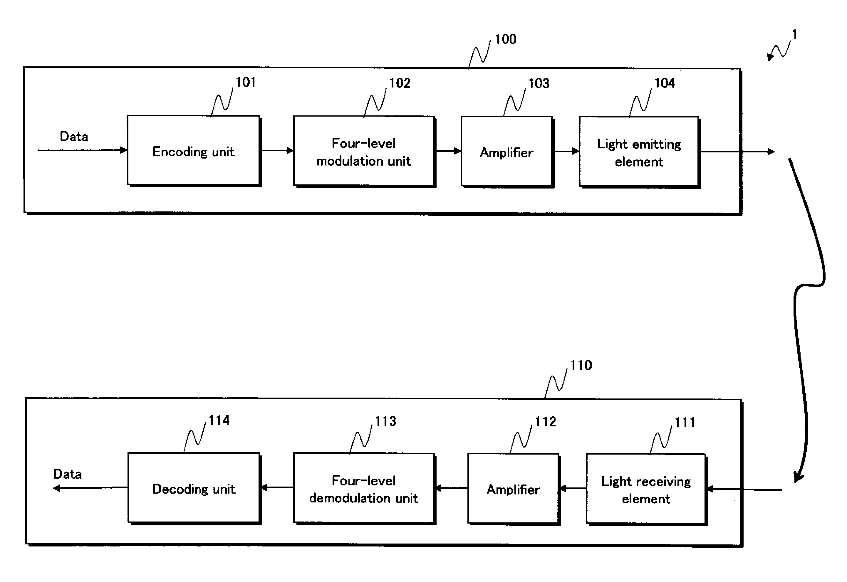
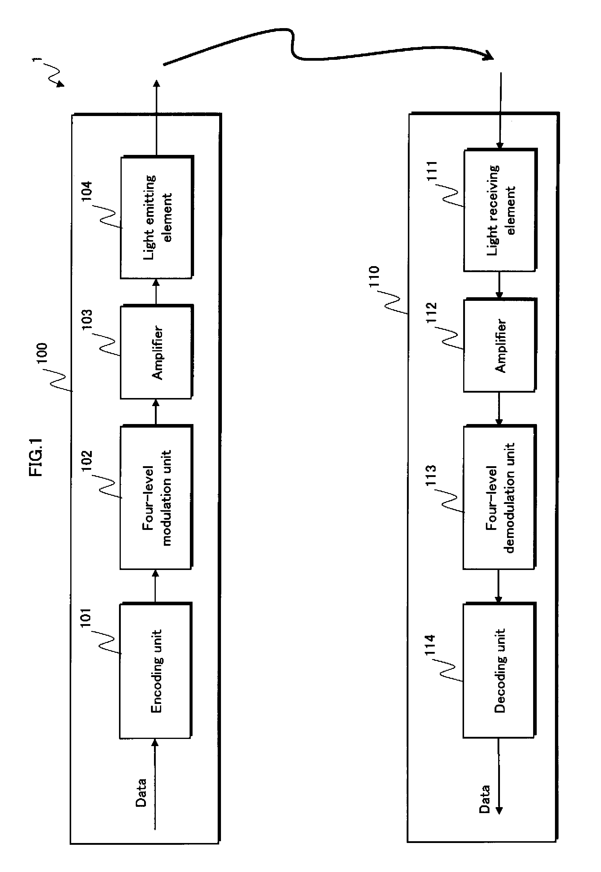
[0084]As shown in FIG. 1, the transmission / reception system 1 is composed of a transmission device 100 and a reception device 110.

[0085]The transmission device 100 applies encoding and either two-level (2̂1) or four-level (2̂2) amplitude modulation to input data that is to be transmitted, thereafter transmitting the data to the reception device 110.

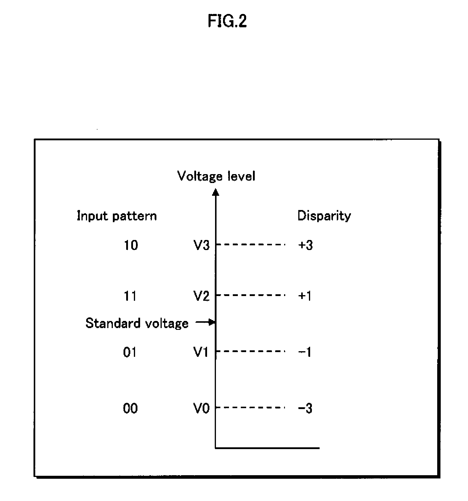
[0086]In Embodiment 1, four-level Amplitude Shift Keying (ASK) modulation is used for four-level amplitude modulation. FIG. 2 shows an example of mapping when using four-level ASK modulation. FIG. 2 shows voltage levels (V0, V1, V2, V3) and disparities (−3, −1, +1, +3) corresponding to input patterns (the values “00”, “01”, 10″, “11”). He...

embodiment 2

2. Embodiment 2

[0226]The following is an explanation of Embodiment 2 of the present invention with reference to the figures, focusing on the aspects that differ from Embodiment 1. Note that the same labels are used for structural elements that perform the same operations.

[0227]As shown in FIG. 11, the transmission / reception system 1a in Embodiment 2 is composed of a transmission device 100a and a reception device 110a.

[0228]As in Embodiment 1, in the following description, before the transmission device 100a actually transmits data that is to be transmitted, both devices transmit and receive, as an initialization process, data to establish communication. Also as in Embodiment 1, the reception device 110a transmits modulation designation data that designates either two-level or four-level amplitude modulation to the transmission device 100a. The transmission device 100a performs modulation on the data to be transmitted in accordance with the amplitude modulation designated by the am...


PUM


Abstract

The present invention aims to provide a transmission device that, in a communication system using multilevel modulation with 2̂n levels (n being an integer greater than or equal to two), limits the run length to a predetermined value or less and guarantees DC balance.
The transmission device, which transmits data to which 2̂n amplitude modulation has been applied, separates data for transmission into n data sequences; encodes one of the n data sequences to guarantee run length, thereby generating a converted data sequence; generates an intermediate data sequence by either inverting or not inverting a specific data sequence so that, based on candidate data, the next output voltage guarantees DC balance; and applies 2̂n amplitude modulation to n-bit symbols each of which has a bit in the intermediate data sequence as a most significant bit and bits in the remaining data sequences, excluding the specific data sequence, as subsequent bits.

Description

[0001]The disclosure of Japanese Patent Application No. 2009-028370 filed Feb. 10, 2009 including specification, drawings and claims is incorporated herein by reference in its entirety.BACKGROUND OF THE INVENTION[0002](1) Field of the Invention[0003]The present invention relates to a transmission device and transmission method that use a multilevel modulation system to transmit and receive data via a wire or wireless channel.[0004](2) Description of the Related Art[0005]One type of encoder used in a transmission device that uses a two-level modulation system is the 8B / 10B encoder disclosed in Patent Literature 1. For an eight-bit sequence that is input, the 8B / 10B encoder limits the maximum number of identical consecutive values to a predetermined value or less (hereinafter, “guarantee the run length”) and outputs a 10-bit encoded bit sequence for which the difference in the number of occurrences of two modulation conditions in a specified period of time is limited to a predetermine...

Claims


Application Information

Patent Timeline
IPC IPC(8): H04L25/49H04L25/34
CPCH04L25/4919H04L25/4917
Inventor TAKAHASHI, HIROSHIOHNISHI, TOSHIAKIANDO, KAZUHIRO
Owner PANASONIC CORP
Why Eureka
Try Eureka