Synthetic resin-made thrust sliding bearing

a thrust bearing and resin-made technology, applied in the direction of sliding contact bearings, mechanical equipment, transportation and packaging, etc., can solve the problems of heavy steering operation, and difficult to maintain a smooth steering operation, so as to maintain sliding characteristics and low friction characteristics

Inactive Publication Date: 2010-08-12
OILES CORP
View PDF7 Cites 16 Cited by
  • Summary
  • Abstract
  • Description
  • Claims
  • Application Information

AI Technical Summary

Benefits of technology

[0027]According to the invention, if it is assumed that an outside diameter of the outer peripheral surface of the first annular projection is c, the inside diameter of the inner peripheral surface of the second annular projection is d, the diameter of the inner peripheral surface of the circular hole of the thrust sliding bearing piece is a, the diameter of the outer peripheral surface of the disk is b, the thickness of the thrust sliding bearing piece corresponding to the depth of the annular recess from the bottom surface to the opening thereof is f, and the thickness of the thrust sliding bearing piece is e, then the sum (A) of volumes of the annular clearances (A1) and (A2) and the volume (B) of that portion of the thrust sliding bearing piece which projects from the opening of the annular recess are in a relationship of e(b2−a2)>f(d2−c2). Therefore, it is possible to provide a synthetic resin-made thrust sliding bearing in which, even in cases where creep deformation has occurred to the sliding bearing piece, sliding can constantly be effected through the sliding bearing piece without shifting to sliding between the upper and lower casings, thereby making it possible to maintain the sliding characteristics such as low friction characteristics and wear resistance for extended periods of time.
[0028]Hereafter, a more detailed description will be given of the present invention with reference to preferred embodiments shown in the drawings. It should be noted that the present invention is not limited to these embodiments.

Problems solved by technology

However, the rolling bearing has a possibility of causing a fatigue failure in the balls or needles owing to such as infinitesimal oscillations and a vibratory load, so that there is a problem in that it is difficult to maintain a smooth steering operation.
As compared with the rolling bearing, the thrust sliding bearing has a high frictional torque and therefore has the problem that the steering operation is made heavy.
Furthermore, both bearings have the problem that the steering operation is made heavy due to the high frictional force of a dust seal formed of an elastomer fitted to prevent the ingress of foreign objects such as dust onto sliding surfaces, and the synthetic resin-made sliding bearing in particular has the problem that the steering operation is made much heavier.

Method used


Image

  • Synthetic resin-made thrust sliding bearing
  • Synthetic resin-made thrust sliding bearing
  • Synthetic resin-made thrust sliding bearing

Examples


first embodiment

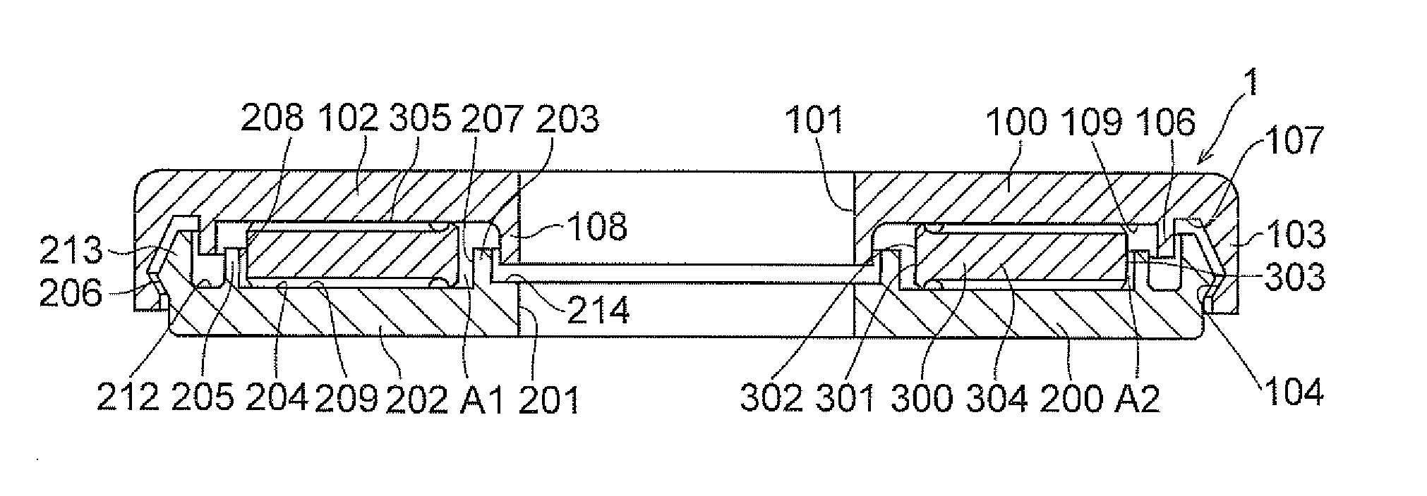
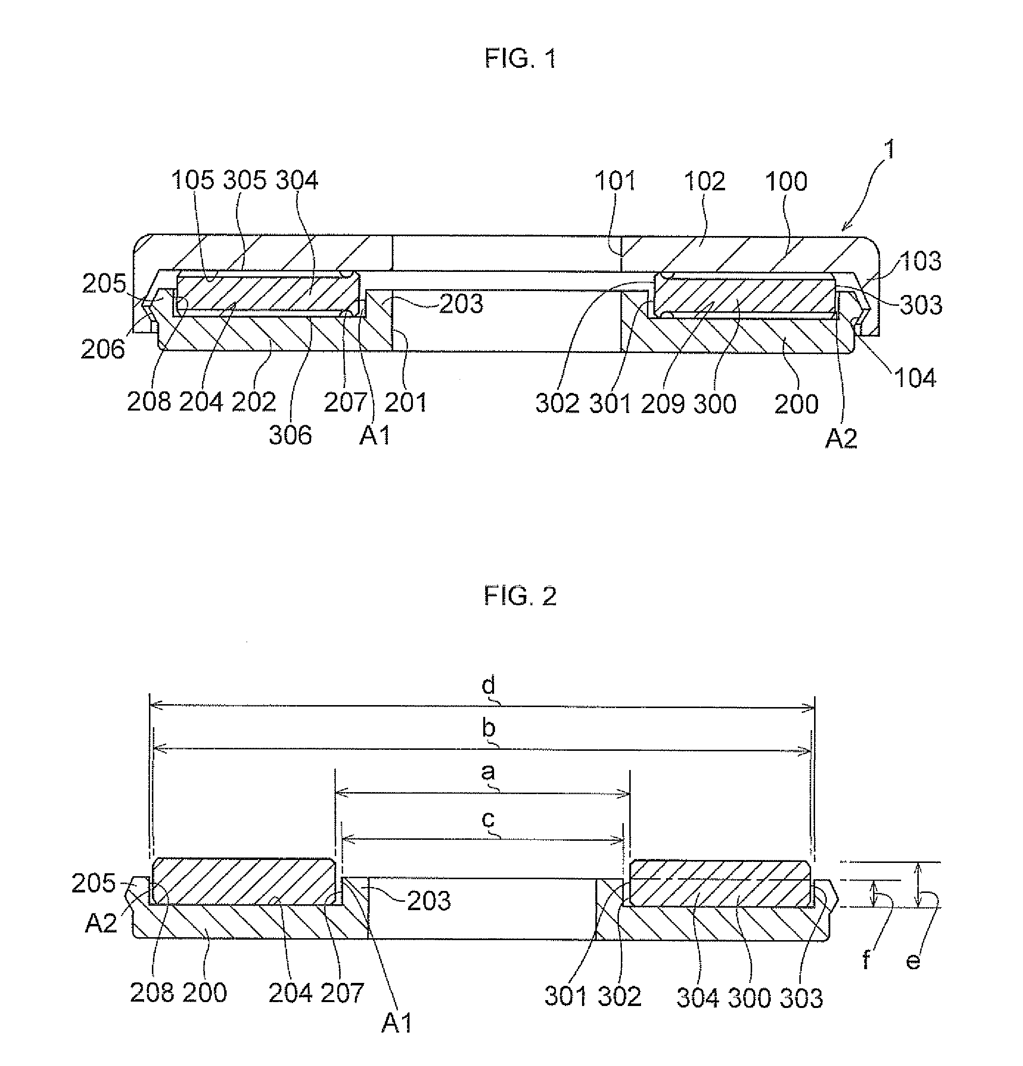
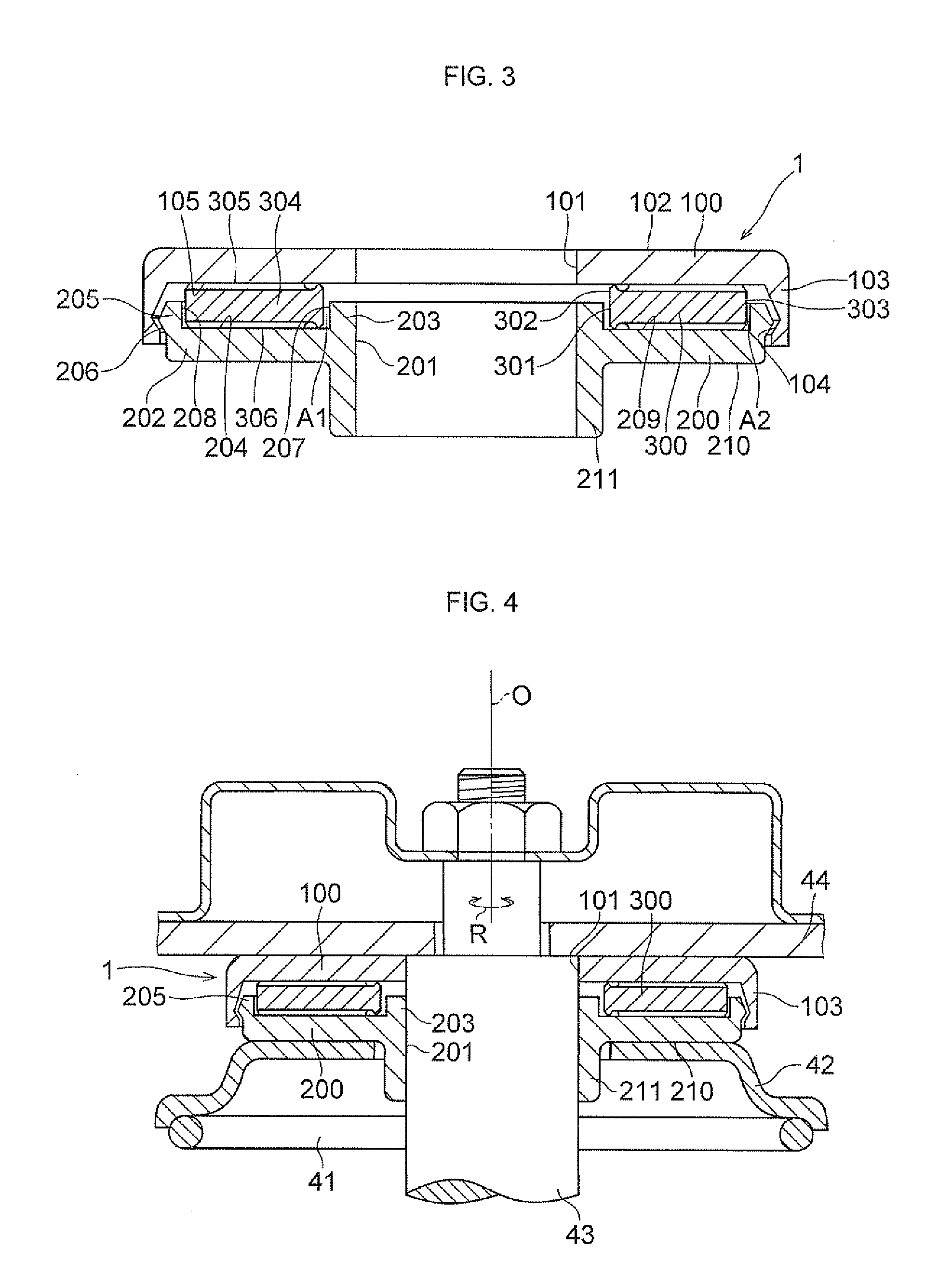
[0041]In FIGS. 1 and 2, a synthetic resin-made thrust sliding bearing 1 in accordance with the invention is comprised of a synthetic resin-made upper casing 100, a synthetic resin-made lower casing 200, and a synthetic resin-made thrust sliding bearing piece 300 interposed between the upper and lower casings 100 and 200.

[0042]The upper casing 100 includes an annular flat portion 102 having a circular hole 101 in its central portion; a cylindrical engaging suspended portion 103 formed integrally at an outer peripheral edge of the annular flat portion 102; and an engaging hook portion 104 formed on an inner peripheral surface of an end portion of the cylindrical engaging suspended portion 103.

[0043]The lower casing 200 includes an annular flat portion 202 having in its central portion an insertion hole 201 of the same diameter as that of the circular hole 101 of the upper casing 100; a first annular projection 203 having an inside diameter identical to that of the insertion hole 201 a...

third embodiment

[0054]FIGS. 5 and 6 show the synthetic resin-made thrust sliding bearing 1 in accordance with the invention. Such a synthetic resin-made thrust sliding bearing 1 is comprised of the synthetic resin-made upper casing 100, the synthetic resin-made lower casing 200, and the synthetic resin-made thrust sliding bearing piece 300 interposed between the upper and lower casings 100 and 200. The upper casing 100 includes the annular flat portion 102 having the circular hole 101 in its central portion; a cylindrical suspended portion 106 formed integrally with a lower surface 105 of the annular flat portion 102 in such a manner as to be radially outwardly spaced apart a predetermined interval from the peripheral edge of the circular hole 101; the cylindrical engaging suspended portion 103 formed integrally at the outer peripheral edge of the annular flat portion 102 in such a manner as to be radially outwardly spaced apart a predetermined interval from the cylindrical suspended portion 106, s...

fourth embodiment

[0060]FIGS. 7 and 8 show the synthetic resin-made thrust sliding bearing 1 in accordance with the invention. Such a synthetic resin-made thrust sliding bearing 1 is comprised of the synthetic resin-made upper casing 100, the synthetic resin-made lower casing 200, and the synthetic resin-made thrust sliding bearing piece 300 interposed between the upper and lower casings 100 and 200. The upper casing 100 includes the annular flat portion 102 having the circular hole 101 in its central portion; a first cylindrical suspended portion 108 formed integrally with the lower surface of the annular flat portion 102 and having an inside diameter identical to that of the circular hole 101; a second cylindrical suspended portion 106 formed integrally with the lower surface of the annular fiat portion 102 in such a manner as to be radially outwardly spaced apart a predetermined interval from the outer peripheral surface of the first cylindrical suspended portion 108, so as to form an annular rece...


PUM

PropertyMeasurementUnit
diameteraaaaaaaaaa
thicknessaaaaaaaaaa
frictional torqueaaaaaaaaaa

Abstract

A synthetic resin-made thrust sliding bearing includes a synthetic resin-made upper casing 100, a synthetic resin-made lower casing 200, and a synthetic resin-made thrust sliding bearing piece 300 interposed between the upper and lower casings 100 and 200.

Description

TECHNICAL FIELD[0001]The present invention relates to a synthetic resin-made thrust sliding bearing, and more particularly to a synthetic resin-made thrust sliding bearing which is suitably incorporated as a thrust sliding bearing of a strut-type suspension (Macpherson type) in a four-wheeled motor vehicle.BACKGROUND ART[0002][Patent Document 1] JP-UM-B-4-52488[0003][Patent Document 2] JP-UM-B-2-1532[0004][Patent Document 3] JP-UM-B-2-6263[0005][Patent Document 4] JP-UM-B-8-2500[0006][Patent Document 5] JP-UM-B-4-47445[0007]In general, a strut-type suspension is mainly used in a front wheel of a four-wheeled motor vehicle, and is constructed such that a strut assembly incorporating a hydraulic shock absorber in a cylinder formed integrally with a main shaft is combined with a coil spring. Among such suspensions, there is a type of structure in which the axis of the coil spring is actively offset with respect to the axis of the strut, so as to allow the sliding of a piston rod of the...

Claims


Application Information

Patent Timeline
Patent Type & Authority Applications(United States)
IPC IPC(8): F16C33/10
CPCB60G15/063B60G15/068B60G2202/312B60G2204/124B60G2204/128F16C2326/05B60G2206/7104F16C17/04F16C33/20F16C33/74B60G2204/418F16C2208/60F16C2208/70F16C2208/76
Inventor KANEKO, RYOHEI
Owner OILES CORP
Why Eureka
Try Eureka