Laser illumination device

Active Publication Date: 2010-08-12
DIGILENS
View PDF5 Cites 151 Cited by
  • Summary
  • Abstract
  • Description
  • Claims
  • Application Information

AI Technical Summary

Benefits of technology

[0020]It is a first object of the present invention to provide an ES

Problems solved by technology

Laser displays suffer from speckle, a sparkly or granular structure seen in uniformly illuminated rough surfaces.
Speckle reduces image sharpness and is distracting to the viewer.
However, the value of M is limited by the numerical aperture of the imaging optics.
Even a perfect optical system cannot do better than to reproduce it exactly.
This is due to fundamental information theory limitations and not any practical optical consideration
Suppression of subjective speckle is more difficult.
Angular diversity would not produce good results, since none of the wave fronts would be overlapping and interfering.
In the near f

Method used


Image

  • Laser illumination device
  • Laser illumination device
  • Laser illumination device

Examples


Embodiment Construction

[0164]It is a first object of the present invention to provide an ESBG despeckler device that can overcome the problem of laser speckle.

[0165]It is a second object of the present invention to provide a compact, efficient laser display incorporating an ESBG despeckler device that can overcome the problem of laser speckle.

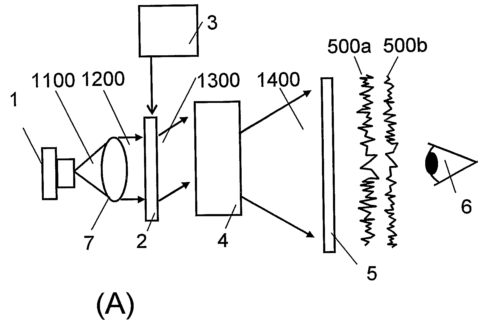
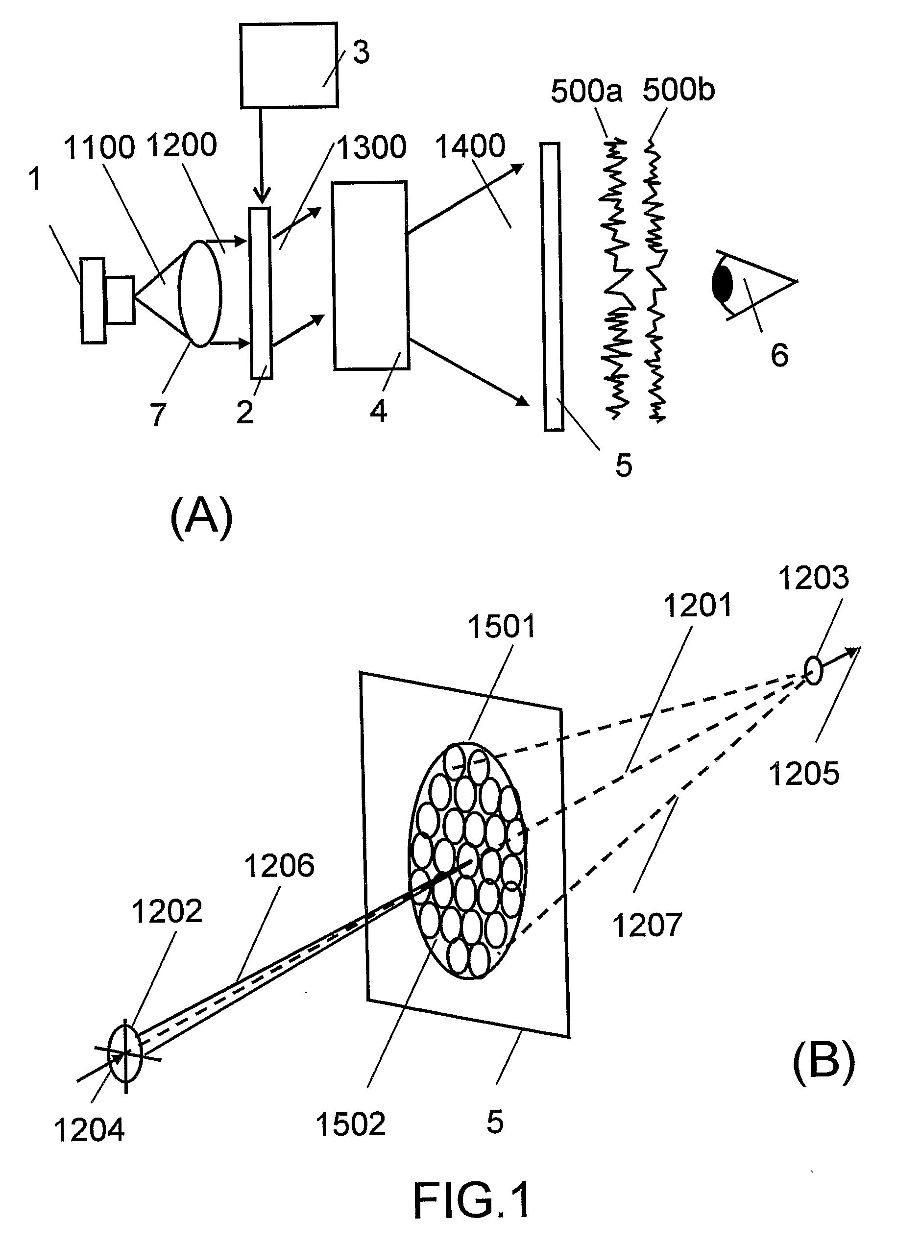
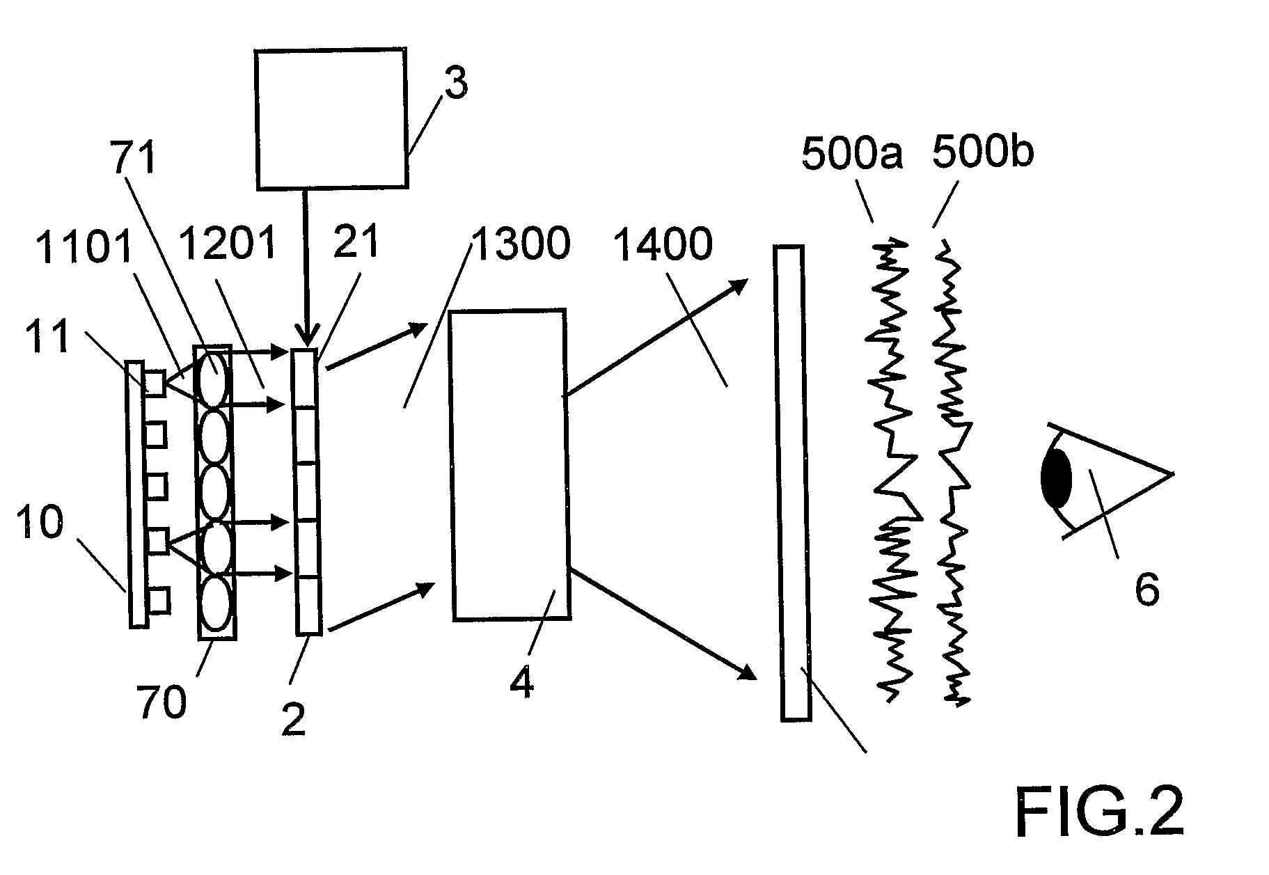
[0166]To assist in clarifying the basic principles of the despeckler device the invention will be described in relation to a practical laser display which comprises a laser source comprising one or more red, green or blue laser die, a flat panel microdisplay and projection optics. It will be clear that the despeckler embodiment to be described is not restricted to application in laser display configurations of the type described.

[0167]For the purposes of explaining the invention an ESBG despeckler device will be understood to comprise one or more ESBGs layers or cells each comprising an ESBG encapsulated between parallel transparent glass walls according to the princ...


PUM

PropertyMeasurementUnit
Angleaaaaaaaaaa
Currentaaaaaaaaaa
Currentaaaaaaaaaa

Abstract

An Electrically Switchable Bragg Grating (ESBG) despeckler device comprising at least one ESBG element recorded in a hPDLC sandwiched between transparent substrates to which transparent conductive coatings have been applied. At least one of said coatings is patterned to provide a two-dimensional array of independently switchable ESBG pixels. Each ESBG pixel has a first unique speckle state under said first applied voltage and a second unique speckle state under said second applied voltage.

Description

CROSS REFERENCE TO RELATED APPLICATIONS[0001]This application incorporates by reference in its entirety a PCT US2006 / 043938 filed 13 Nov. 2006, claiming priority to U.S. provisional patent application 60 / 789,595 filed on 6 Apr. 2006, entitled METHOD AND APPARATUS FOR PROVIDING A TRANSPARENT DISPLAY.[0002]This application incorporates by reference in their entireties U.S. provisional patent applications:Ser. No. 60 / 935,109 filed 26 Jul. 2007, entitled LASER DISPLAYS;Ser. No. 61 / 071,230 filed 18 Apr. 2008, entitled SCROLLING ILLUMINATOR;Ser. No. 61 / 071,229 filed 18 Apr. 2008, entitled SCROLLING FLAT PANEL DISPLAY; andSer. No. 61 / 071,232 filed 18 Apr. 2008 DUAL SCREEN PROJECTION DISPLAY 33.This application incorporates by reference in its entirety the United Kingdom patent application GB0718706.5 filed 25 Sep. 2007.BACKGROUND OF THE INVENTION[0003]The present invention relates to an illumination device, and more particularly to a laser illumination device based on electrically switchab...

Claims


Application Information

Patent Timeline
IPC IPC(8): G02F1/295
CPCG02B27/48G02F1/133606G02F1/13342G03H1/32G02F1/0136G03B21/2033G02B5/1828G02B6/0023G02B6/0035G02B6/005G02B27/425G02F1/133553G02F1/13731G02F2203/62G03H1/0248
Inventor POPOVICH, MILAN MOMCILOWALDERN, JONATHAN DAVIDSTOREY, JOHN JAMES
Owner DIGILENS
Why Eureka
Try Eureka