Diagnostic system and method for monitoring a rail system

a technology of rail system and diagnostic system, which is applied in the direction of vehicle position/course/altitude control, process and machine control, instruments, etc., can solve the problems of system not taking advantage of data acquired from rail infrastructure for identifying faults on rail vehicles

Inactive Publication Date: 2010-08-12
BOMBARDIER TRANSPORTATION GMBH
View PDF23 Cites 62 Cited by
  • Summary
  • Abstract
  • Description
  • Claims
  • Application Information

AI Technical Summary

Benefits of technology

[0016]Thanks to the merging of rail infrastructure-related data with rail vehicle-related data, it becomes possible to more thoroughly analyse events and to merge data that are correlated, or are likely to have a causal relationship, so as to deliver more relevant failure prediction analyses.

Problems solved by technology

Today, rail system operators are under increasing pressure to keep their trains running on time and for longer.
Yet with maintenance regimes typically being mileage or timescale related, as opposed to condition driven, trains can be out of operation for unnecessary servicing, or unforeseen repairs.
Similar issues are also apparent when considering the operation and maintenance of the rail infrastructure (rails, signals, bridges, earthworks, etc)
This system, however, does not take advantage of data acquired from the rail infrastructure itself for identifying faults on the rail vehicles.
Moreover, the system is not able to identify faults relating to the infrastructure of the rail system.
However, this system does not take advantage of data from both mobile and stationary sources.
This document, however, fails to disclose the earlier steps of development of the diagnostic system, i.e. before an accurate predictor becomes available.

Method used


Image

  • Diagnostic system and method for monitoring a rail system
  • Diagnostic system and method for monitoring a rail system
  • Diagnostic system and method for monitoring a rail system

Examples


Embodiment Construction

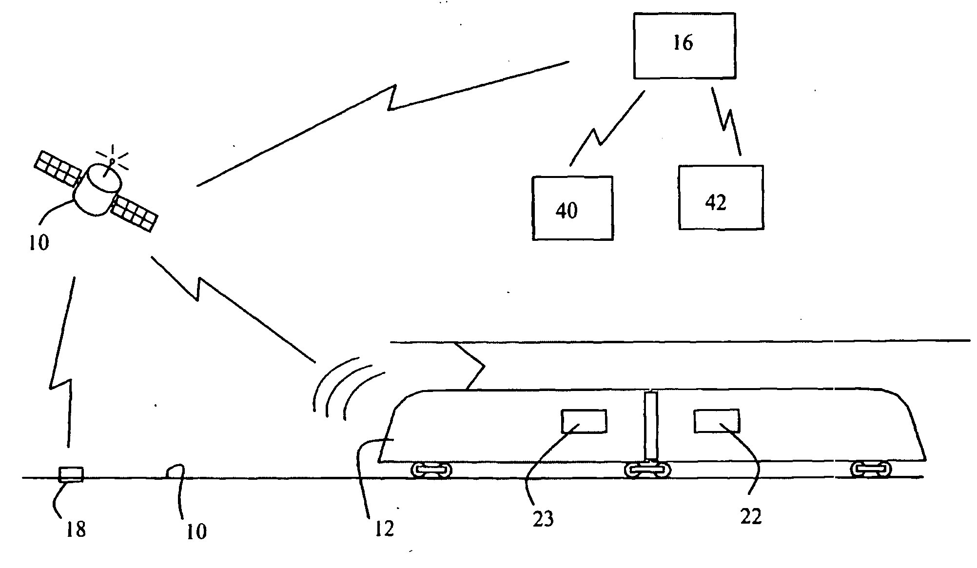
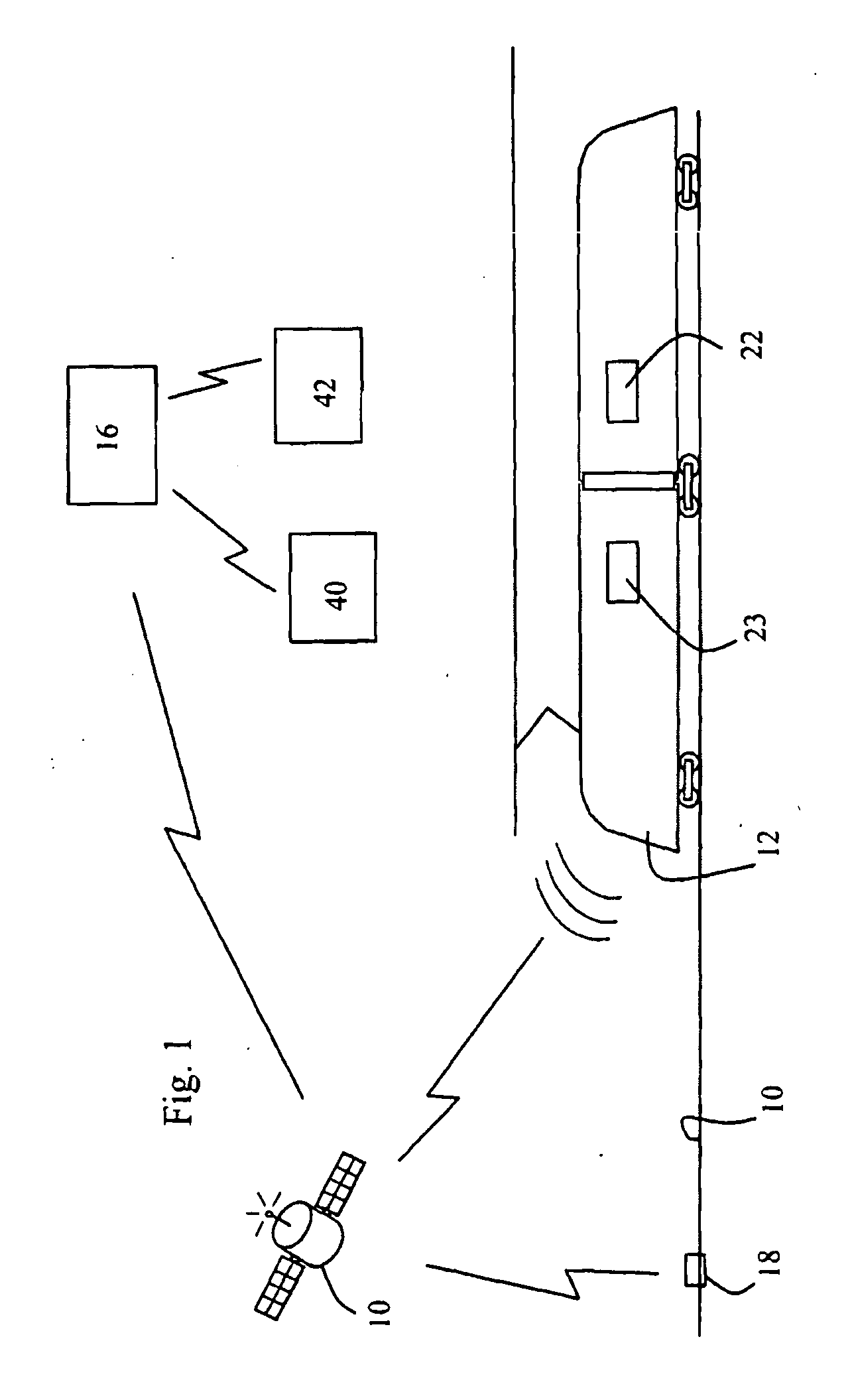
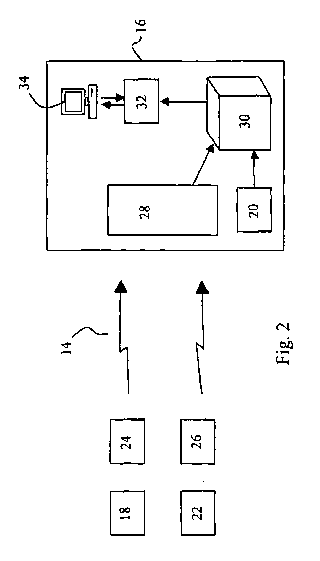
[0032]Referring to FIG. 1, a rail system comprises a rail infrastructure 10 consisting of tracks, junctions, overhead lines, railway stations, maintenance facilities, etc., and one or more fleets of rail vehicles 12 circulating on the tracks. The rail system is also provided with telecommunication means 14 for transmitting information to and from a data centre 16. These communication means may include wireless or hard-wired communications links such as a satellite system, cellular network, optical or infrared system or hard-wired phone line.

[0033]The rail infrastructure 10 is equipped with sensors 18 for monitoring events, linked to the data centre via the communication means. The monitored events can be related to one component of the rail infrastructure or to environmental conditions. By essence, these rail infrastructure-related sensors 18 are fixed and their position is known and stored in a database 20 of the data centre. Examples of such sensors are listed in table 1 below.

TAB...


PUM


Abstract

The vehicles (12) of at least one fleet of rail vehicles are provided with on-board sensors (22) and rail vehicle positioning means (23). The rail infrastructure on which the rail vehicles circulate is provided with fixed rail infrastructure sensors (18). The rail infrastructure-related sensor data is merged with the rail vehicle-related sensor data, with location data representative of the location of the rail infrastructure-related sensors and with the rail vehicle position data for generating series of categorized event data representative of the occurrence of categorized events at a given location on the rail infrastructure over time and/or on a given rail vehicle of the fleet over time. The series of categorized events data representative of at least one category of events can be compared over any predetermined period of time to identify any location of the rail infrastructure and/or any rail vehicle which exhibits a series of events data that is significantly different from the other locations of the rail infrastructure and/or rail vehicles of the fleet over said predetermined period of time.

Description

TECHNICAL FIELD OF THE INVENTION[0001]The invention relates to a diagnostic system and a method for monitoring a rail system comprising a rail infrastructure and at least one fleet of rail vehicles circulating on the rail infrastructure, and for identifying particular faults relating to components of the rail system.BACKGROUND ART[0002]Today, rail system operators are under increasing pressure to keep their trains running on time and for longer. Passenger expectations for comfort are greater than ever whilst increasingly sophisticated equipment creates both new challenges and opportunities for the rail system operator and its maintenance teams. The efficiency of any rail company hinges on the safety, reliability and availability of its trains. Yet with maintenance regimes typically being mileage or timescale related, as opposed to condition driven, trains can be out of operation for unnecessary servicing, or unforeseen repairs. Similar issues are also apparent when considering the o...

Claims


Application Information

Patent Timeline
Patent Type & Authority Applications(United States)
IPC IPC(8): B61L27/00G06F19/00
CPCB61L27/0094B61L27/57
Inventor FORREST, PAULPROVOST, MICHAELLOVELL, JEREMY
Owner BOMBARDIER TRANSPORTATION GMBH
Why Eureka
Try Eureka