Compander System

a compander and expander technology, applied in the direction of speech analysis, volume compression/expansion in digital/coded amplifiers, instruments, etc., can solve the problems of reduced dynamic range, inability to prevent audible noise, and latency at both ends, so as to achieve substantial noise change without latency

Active Publication Date: 2010-08-12
SENNHEISER ELECTRONICS GMBH & CO KG
View PDF9 Cites 3 Cited by
  • Summary
  • Abstract
  • Description
  • Claims
  • Application Information

AI Technical Summary

Benefits of technology

[0011]Therefore, it is the primary object of the present invention to provide a compressor device, an expander device and a compander system which changes noise substantially without latency.

Problems solved by technology

As a result of this reduced dynamic range, audible noise cannot be prevented.
However, the main disadvantage of this method is the latency at both ends due to the block-based processing.

Method used


Image

  • Compander System
  • Compander System
  • Compander System

Examples


Embodiment Construction

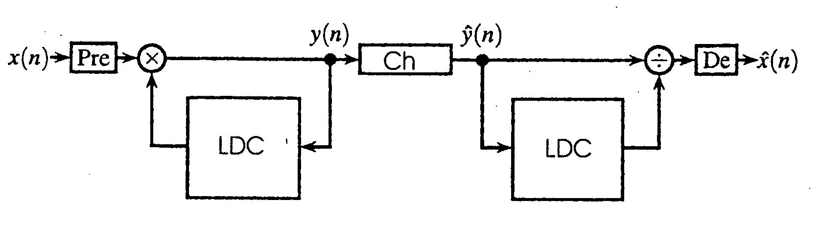
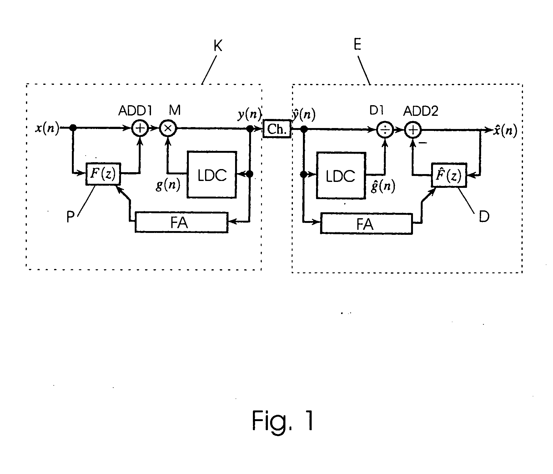
[0026]FIG. 1 shows a block diagram of a compander system according to a first embodiment example. The compander system substantially comprises a compressor K, a transmission channel Ch, and an expander E. The compressor K has a level detecting / control device LDC, a filter P for pre-emphasis filtering, and a filter adaption unit FA. The expander E likewise has a level detecting / control unit LDC, a filter D for de-emphasis filtering, and a filter adaption unit FA.

[0027]The input signal, preferably an audio signal x(n), is fed to the adding unit ADD1 on the one hand and to the filter P on the other hand. In the filter P, a pre-emphasis filtering is carried out based on the output of the filter adaption unit FA. The output of the filter P is added to the input signal x(n) in the adding unit ADD1. The result of this addition is fed to a multiplying unit M, where the result of the addition is multiplied by a signal g(n). The multiplication results in the output signal y(n). This output si...


PUM


Abstract

A compressor device for a compander system has a level detecting/control device and a pre-emphasis device for carrying out an adaptive pre-emphasis filtering. The invention is also directed to an expander device for a compander system with a level detecting/control device and a de-emphasis device for carrying out an adaptive de-emphasis filtering.

Description

CROSS-REFERENCE TO RELATED APPLICATIONS[0001]This is a national phase application of International Application No. PCT / EP2006 / 003076, filed Apr. 5, 2006 which claims priority of German Application No. 10 2005 015 647.9, filed Apr. 5, 2005, the complete disclosures of which are hereby incorporated by reference.BACKGROUND OF THE INVENTION[0002]a) Field of the Invention[0003]The present invention is directed to a compressor device, an expander device, and a compander system and to a corresponding transmission method.[0004]b) Description of the Related Art[0005]Compander systems are known, for example, from the sphere of cassette recorders or analog FM radio transmission systems for suppressing noise and increasing the dynamic range. A digital implementation of a system of this kind was described by Peissig et al. in “Digital emulation of analog companding algorithms for FM radio transmission”, DAFX-04 Conference on Digital Audio Effects, pages 285-290, Naples, Italy, 2004. For this pur...

Claims


Application Information

Patent Timeline
Patent Type & Authority Applications(United States)
IPC IPC(8): G10L19/00G10L21/02G10L21/0264
CPCG10L21/0264H03G7/007H03G9/06H03G9/005H03G9/00
Inventor PEISSIG, JUERGENZOELZER, UDOKEILER, FLORIANHOLTERS, MARTIN
Owner SENNHEISER ELECTRONICS GMBH & CO KG
Why Eureka
Try Eureka