Application workflow integration subsystem

a workflow and application technology, applied in the computer field, can solve the problems of complex and non-scalable system of application program interfaces, multiple vm application code bases, and much greater effort required for vm software maintenance and upgrades

Active Publication Date: 2010-08-12
IBM CORP
View PDF18 Cites 42 Cited by
  • Summary
  • Abstract
  • Description
  • Claims
  • Application Information

AI Technical Summary

Benefits of technology

[0005]To address the above described issue, a computer-implemented method, system and computer program product for integrating applications into a workflow are presented. Execution of a first application, which is generated by a first application engine, is initiated. The first application performs a first subtask that is depicted by a first component of a flow-chart that has been previously generated by a Business Process Management (BPM) engine. A Workflow Integration Subsystem (WIS), which provides an interface between a BPM engine and multiple application engines, locates and selects the specific application engine (based on the first subtask in the flow-chart) that will perform the first subtask. The BPM engine then calls other application engines to perform other subtasks that supplement the first subtask, such that the first subtask and the other subtasks combine to perform an entire task depicted by the flow-chart. Although only one BPM engine will be deployed for a given installation, the WIS allows for easy integration with a variety of commercially available BPM engines in order to meet customer preference and changing “best-of-breed” BPM offerings.

Problems solved by technology

Current processes require a complex and non-scalable system of Application Program Interfaces (APIs) to call the back-office applications.
Building such custom integration solutions usually results in multiple VM application code bases and much greater effort required for VM software maintenance and upgrades.

Method used


Image

  • Application workflow integration subsystem
  • Application workflow integration subsystem
  • Application workflow integration subsystem

Examples


Embodiment Construction

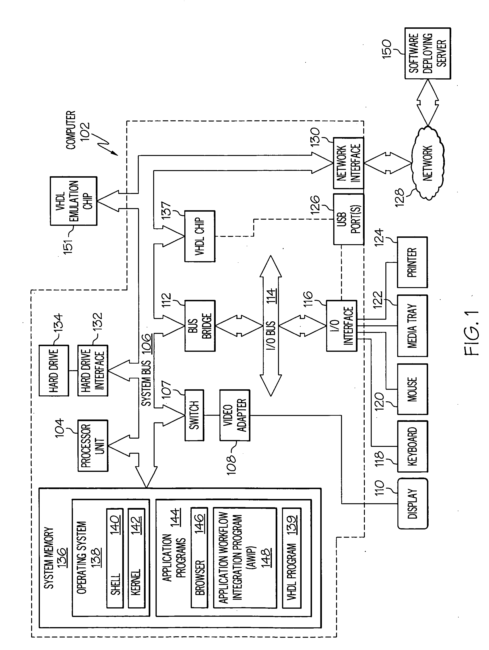
[0014]With reference now to the figures, and in particular to FIG. 1, there is depicted a block diagram of an exemplary computer 102, which may be utilized by the present invention. Note that some or all of the exemplary architecture shown for computer 102 may be utilized by software deploying server 150.

[0015]Computer 102 includes a processor unit 104 that is coupled to a system bus 106. Processor unit 104 may utilize one or more processors, each of which has one or more processor cores. A video adapter 108, which drives / supports a display 110, is also coupled to system bus 106. In one embodiment, a switch 107 couples the video adapter 108 to the system bus 106. Alternatively, the switch 107 may couple the video adapter 108 to the display 110. In either embodiment, the switch 107 is a switch, preferably mechanical, that allows the display 110 to be coupled to the system bus 106, and thus to be functional, only upon execution of instructions (e.g., Application Workflow Integration P...


PUM


Abstract

A computer-implemented method, system and computer program product for integrating an application engine with processes depicted by a flow-chart created by a Business Process Management (BPM) engine are presented. Execution of a first application, which is generated by a first application engine, is initiated. The first application performs a first subtask that is depicted by a first component of a flow-chart that has been previously generated by the BPM engine. A Workflow Integration Subsystem (WIS), which provides an interface between the first application engine and the BPM engine, selects the flow-chart that contains the first subtask performed by the first application. The BPM engine calls other application engines to perform other subtasks that supplement the first subtask, such that the first subtask and the other subtasks combine to perform an entire task that is depicted by the flow-chart.

Description

BACKGROUND OF THE INVENTION[0001]1. Technical Field[0002]The present disclosure relates to the field of computers, and specifically to logic for managing processes running on computers.[0003]2. Description of the Related Art[0004]One criterion in which software can be classified is level of specificity. That is, some software is designed for a specific function, while other software is designed for a broader range of functions that may be related to, and may actually include, the specific function of the narrower software. Narrowly designed software may be referenced as a Vertical Market (VM) software application, while an exemplary broader software may be a Business Process Management (BPM) software solution. A BPM software solution is typically based on and / or generates a flowchart of global business processes. For example, a VM software application may be a data entry program used to apply for a land title search, while a BPM software solution may be a tool that allows a user to ...

Claims


Application Information

Patent Timeline
Patent Type & Authority Applications(United States)
IPC IPC(8): G06F9/46
CPCG06F9/485
Inventor LAI, HENRYMARUSIC, STEVEN ANTHONYOCTAVIANO, STEVEN
Owner IBM CORP
Why Eureka
Try Eureka