Configurations And Methods For Improved Natural Gas Liquids Recovery

a technology of natural gas liquid recovery and configuration, applied in the direction of hydrocarbon oil treatment, hydrocarbon oil treatment products, solidification, etc., can solve the problems of high ethane recovery of 80%, inherently limited by the temperature level of refrigerant, and propane refrigeration requires additional capital and operating costs. , to achieve the effect of high propane recovery and reduction of pressur

Active Publication Date: 2010-08-19
FLUOR TECH CORP
View PDF24 Cites 32 Cited by
  • Summary
  • Abstract
  • Description
  • Claims
  • Application Information

AI Technical Summary

Benefits of technology

[0017]Various objects, features, aspects and advantages of the present invention will become more apparent from the following detailed description of preferred embodiments of the invention.

Problems solved by technology

Although Rambo's configuration advantageously reduces capital cost for equipment associated with providing reflux for the absorption section and the de-deethanizer, high ethane recovery of 80% becomes difficult when feed gas pressure is less than 1,000 psig due to lower turbo expansion cooling while reducing absorber pressure.
Moreover, where the gas has a high CO2 content (e.g., greater than 2 mole %) expansion cooling is problematic due to the potential of CO2 freezing in the demethanizer.
Consequently, such plants typically require deep propane refrigeration which, however, is inherently limited by the temperature level of the refrigerant.
Moreover, the propane refrigeration requires additional capital and operating cost and is recognized a safety concern in NGL plants.
High ethane recovery of over 80% are rarely achievable with turbo expansion alone and thus propane refrigeration is required, adding complexity and safety hazards particularly in congested offshore and existing facilities environments.
Although Sorensen's configuration generally provides improved propane recovery, ethane recovery is typically limited to about 20% to 40%.
In most cases, high recoveries are also limited by CO2 freezing in the demethanizer, and propane recovery will drop in most cases when operating on ethane rejection mode.
Most significantly, all or almost all of those configurations require a relatively fixed feed gas composition and typically lack of operational flexibility where a change in ethane recovery is required.
Thus, although various configurations and methods are known to recover natural gas liquids, all or almost all of them suffer from one or more disadvantages.

Method used


Image

  • Configurations And Methods For Improved Natural Gas Liquids Recovery
  • Configurations And Methods For Improved Natural Gas Liquids Recovery

Examples


Embodiment Construction

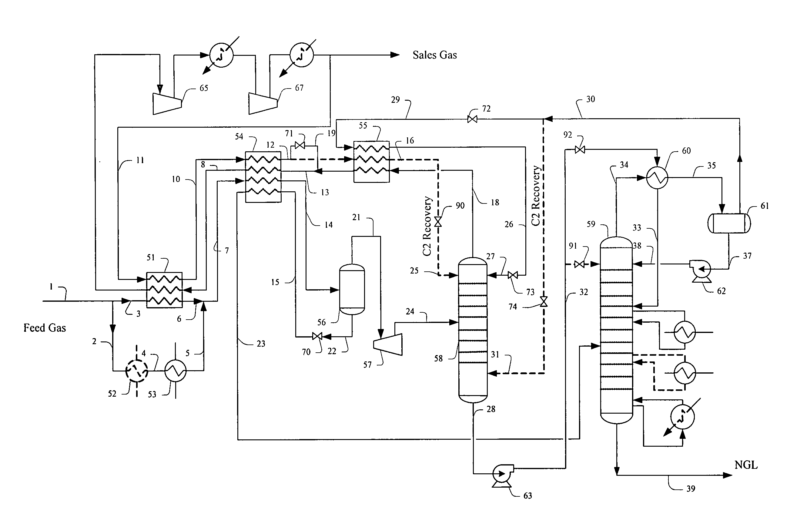
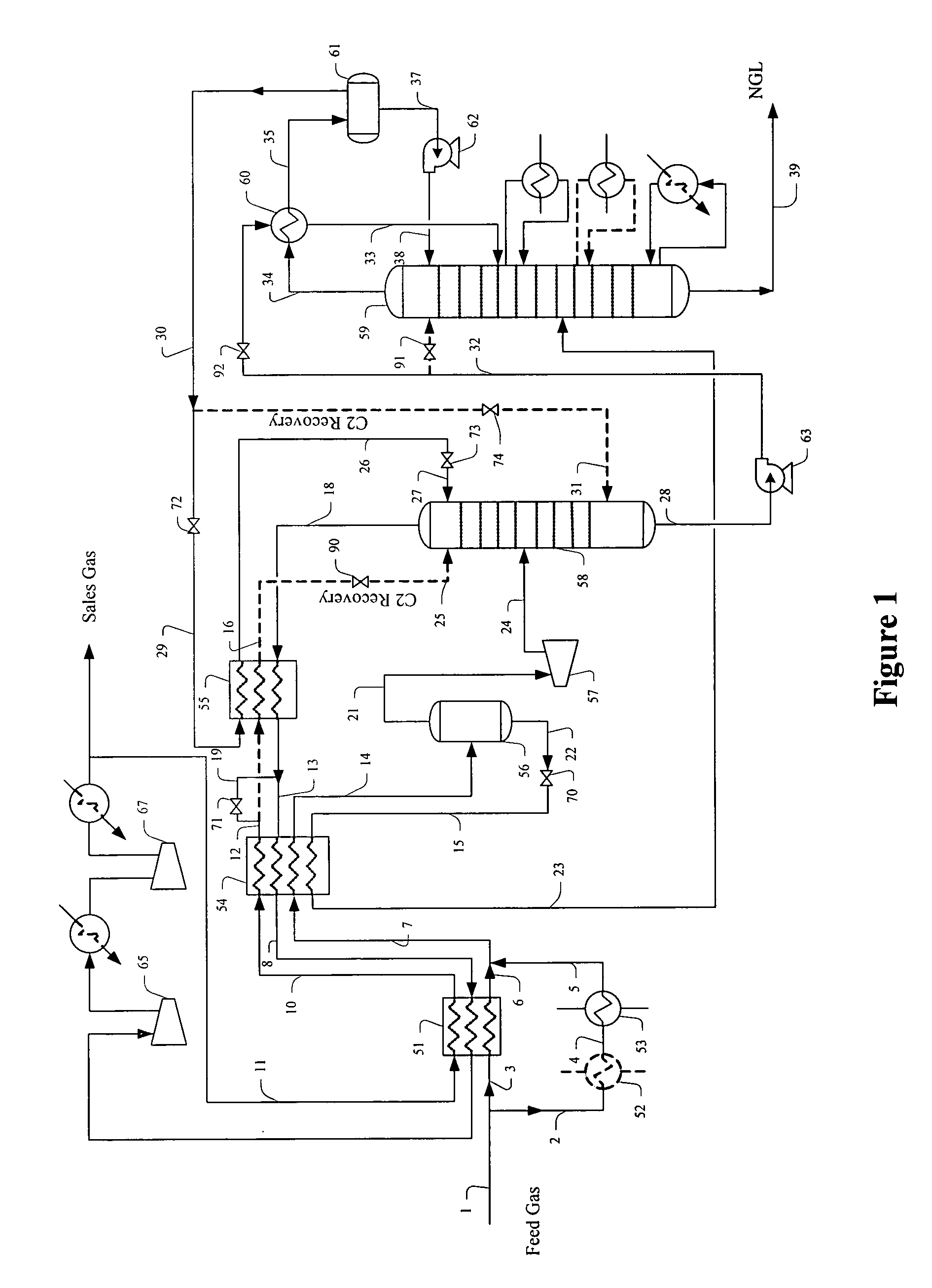
[0019]The inventor has discovered that high NGL recovery (e.g., at least 99% C3 and at least 90% C2) can be achieved in configurations using chilled residue gas recycle in which the plant is configured such that the first column can receive a reflux stream from one of two locations, wherein the reflux stream is selected as a function of the desired NGL recovery. Advantageously, external refrigeration requirements are entirely eliminated in such configurations, and it should be further recognized that contemplated plants and methods will allow variable ethane recovery levels via switching valves that allow selection of one of the two reflux streams.

[0020]Most preferably, contemplated plants and methods employ a two-column NGL recovery configuration having an absorber and a distillation column, and a bypass through which a portion of the residue gas compressor discharge is recycled to thereby eliminate external refrigeration. The absorber is configured to receive two alternate reflux ...


PUM


Abstract

Contemplated plants for recovery of NGL from natural gas employ alternate reflux streams in a first column and a residue gas bypass stream, wherein expansion of various process streams provides substantially all of the refrigeration duty in the plant. Contemplated plants not only have flexible recovery of ethane between 2% and 90% while recovering at least 99% of propane, but also reduce and more typically eliminate the need for external refrigeration.

Description

[0001]This application claims priority to our copending U.S. provisional patent application with the Ser. No. 60 / 955,697, which was filed Aug. 14, 2007.FIELD OF THE INVENTION[0002]The field of the invention is configurations and methods of processing natural gas, especially as it relates to flexible recovery of natural gas liquids (NGL) from natural gas.BACKGROUND OF THE INVENTION[0003]Many natural and synthetic gases comprise a variety of different hydrocarbons, and numerous separation processes and configurations are known in the art to produce commercially relevant fractions from such gases. In a typical gas separation process, a feed gas stream under pressure is cooled by a heat exchanger, typically using propane refrigeration when the feed gas is rich (containing more than 5% C3+ components) and as the gas cools, liquids condense from the cooled gas. The liquids are then expanded and fractionated in a distillation column (e.g., de-deethanizer or demethanizer) to separate residu...

Claims


Application Information

Patent Timeline
Patent Type & Authority Applications(United States)
IPC IPC(8): F25J3/00
CPCF25J3/0209C10G2400/28F25J3/0238F25J3/0242F25J2200/04F25J2200/70F25J2200/74F25J2200/76F25J2200/78F25J2205/04F25J2210/06F25J2240/02F25J2245/02F25J2270/02F25J2280/02C10G5/06F25J3/0233F25J2270/88
Inventor MAK, JOHN
Owner FLUOR TECH CORP
Why Eureka
Try Eureka