
Method and device for monitoring operation of a solar thermal system

a solar thermal and monitoring device technology, applied in lighting and heating apparatus, heating types, instruments, etc., can solve the problems of not being able to compete with the direct purchase of electricity from public power companies, solar cells are often costly, and still certain limitations

Inactive Publication Date: 2010-08-19
FTC SOLAR INC
View PDF29 Cites 57 Cited by
  • Summary
  • Abstract
  • Description
  • Claims
  • Application Information

AI Technical Summary

Benefits of technology

[0017]Many benefits are achieved by way of the present invention over conventional techniques. Providing the user with accurate and reliable information regarding the operation of his/her healthy home system is beneficial, not only from the vantage of keeping the user well-informed and operating parameter modifications to be done, but also from the validation and the confidence of the recorded data in other embodiments. In regards to this latter point, the validated information can play a role in standards for data consist...

Problems solved by technology

Obviously, our daily lives depend, for the most part, upon oil or other forms of fossil fuel, which is becoming scarce as it becomes depleted.
Ultimately, other effects include mass species extinctions, and possibly other uncertainties that may be detrimental to human beings.
Although solar panels have been used successful for certain applications, there are still certain limitations.
Solar cells are often costly.
Depending upon the geographic region, there are often financial subsidies from governmental entities for purchasing solar panels, which often cannot compete with the direct purchase of electricity from public power companies.
Such wafer materials are often costly and difficult to manufacture efficiently on a large scale.
Availability of solar panels is also somewhat scarce.
That is, solar panels are often difficult to find and purchase from limited sources of photovoltaic silicon bearing materials.

Method used


Image

  • Method and device for monitoring operation of a solar thermal system
  • Method and device for monitoring operation of a solar thermal system
  • Method and device for monitoring operation of a solar thermal system

Examples


Embodiment Construction

[0032]According to the present invention, techniques related to operation of a solar system are provided. More particularly, the present invention provides a method and device for operating a solar thermal system through a controller, and displaying information in text, graphical, and animation form. Merely, by way of example, the present invention has been applied to a thermal solar module configured on a building structure, but it would be recognized that the invention has a much broader range of applications.

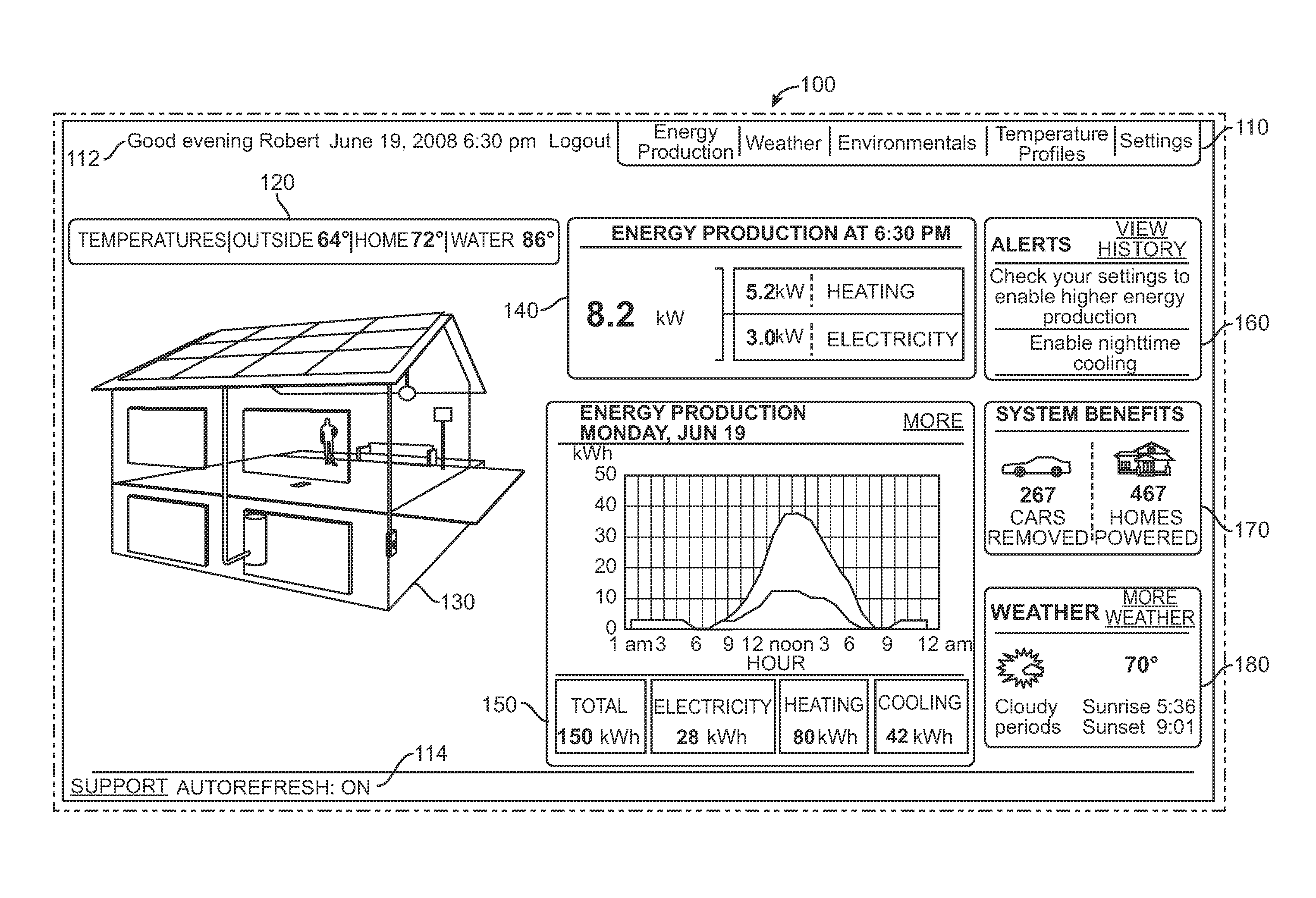
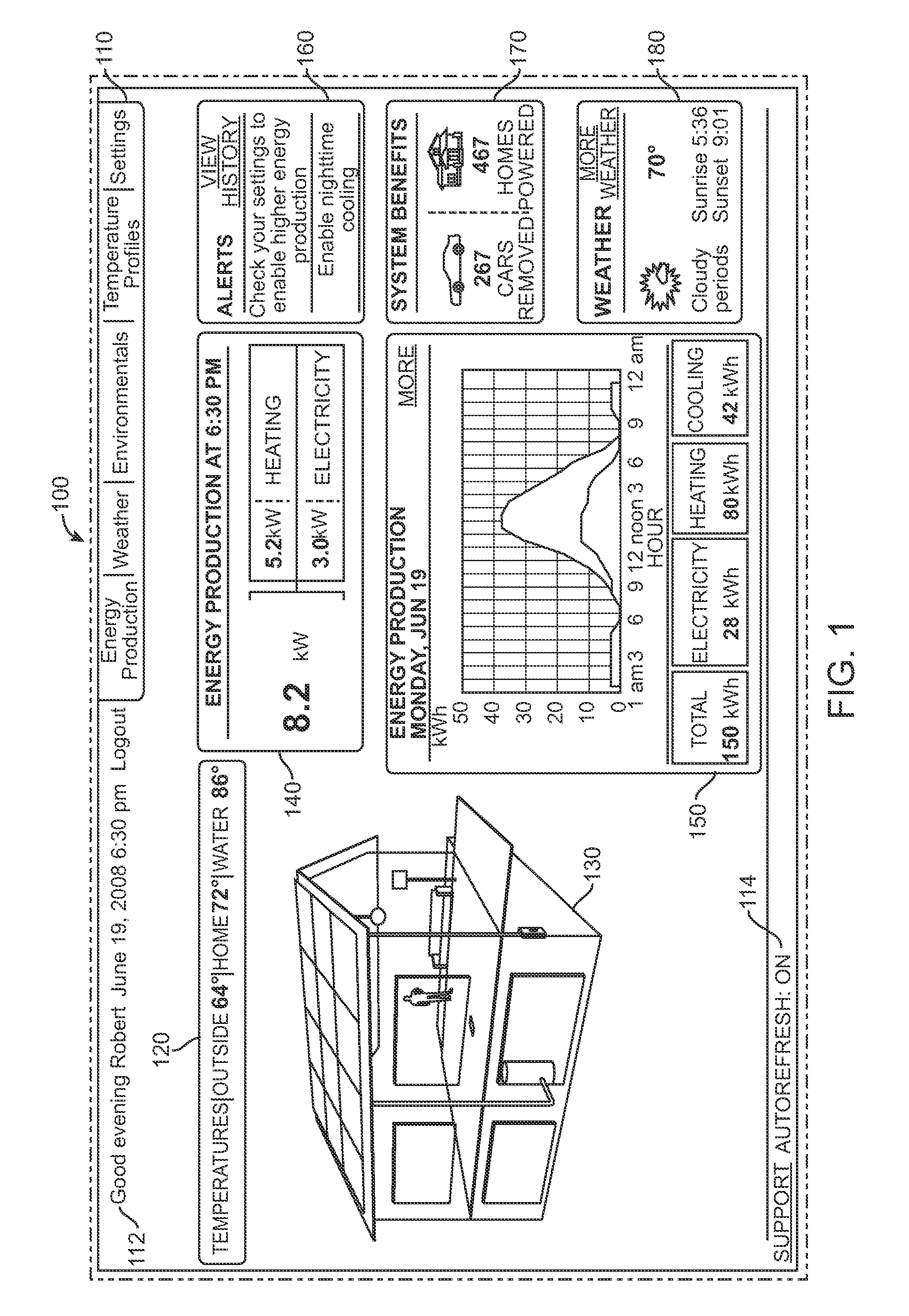
[0033]FIG. 1 is a simplified diagram of a user interface for a display of a healthy home according to an embodiment of the present invention. These diagrams are merely illustrations and should not limit the scope of the claims herein. One of ordinary skill in the art would recognize other variations, modifications, and alternatives. As shown, the graphical user interface 100 is one of many, if not the first, window for the solar thermal operation monitoring system. The user i...


PUM


Abstract

A novel method for monitoring the operation of a solar thermal system such as the healthy home system or the like. The present device includes a hardware housing with a processor device coupled to a bus and one or more memory devices. The processor device can be coupled to one or more input devices wherein the one or more input devices are coupled to at least the solar array. The input devices can be coupled to the electric panel, the space heater, the water heater, as well as other components of the healthy home. The method includes a variety of steps such as establishing connection to associated hardware in the healthy home system, running diagnostic checks to determine system health, validating acquired data, and displaying the data through text display and graphical illustrations. The method also includes updating the system information according to a schedule scheme such as a polling scheme, interrupt scheme, or others. These and possibly other steps can provide an easy and cost effective means of monitoring a healthy home's system operation.

Description

CROSS-REFERENCES TO RELATED APPLICATIONS[0001]This application claims priority to Provisional Application No. 61 / 145,961, filed Jan. 20, 2009, commonly assigned, and incorporated by reference herein for all purpose.BACKGROUND OF THE INVENTION[0002]The present invention relates to operation of a solar system. More particularly, the present invention provides a method and device for operating a solar thermal system through a controller, and displaying information in text, graphical, and animation form. Merely, by way of example, the present invention has been applied to a thermal solar module configured on a building structure, but it would be recognized that the invention has a much broader range of applications such as other photovoltaic solar modules and combinations.[0003]Over the past centuries, the world population of human beings has exploded. Along with the population, demand for resources has also grown explosively. Such resources include raw materials such as wood, iron, and...

Claims


Application Information

Patent Timeline
IPC IPC(8): G06T15/70
CPCF24D19/1042H02S50/10F24J2/40F24S50/00Y02E10/50Y02B10/10
Inventor PLAISTED, JOSHUA REEDLEBLANC, ARTHUR RENEHANDELSMAN, GORDON MICHAELVERONI, CLIVERISSMAN, GLENDACORRIVEAU, DARRELL JOHNING, GARYKIRKPATRICK, PETER
Owner FTC SOLAR INC
Learn More