Variable focus liquid filled lens apparatus

a liquid-filled lens and variable focus technology, applied in the field of consumer ophthalmic lenses, can solve the problems of loss of stereopsis (depth perception), drop in reading speed and comprehension rate, and hasten the onset of fatigu

Inactive Publication Date: 2010-08-19
ADLENS BEACON INC
View PDF96 Cites 51 Cited by
  • Summary
  • Abstract
  • Description
  • Claims
  • Application Information

AI Technical Summary

Benefits of technology

[0010]In accordance with the objects of the invention, a liquid-filled lens for consumer, ophthalmic applications is provided. The lens has a front member that is rigid provided by an optic made of glass or plastic, a back surface comprising a flexible membrane stretched over the edge of the rigid optic, and a fluid filling the cavity formed between the front optic and the flexible membrane. The liquid-filled lens may comprise one or more liquid filled cavities, contained by a corresponding number of membranes. Each liquid filled cavity is sealed, and is under a positive pressure in order to maintain the membrane in a stretched state. The front optic may have an aspheric surface geometry and may have a meniscus shape.

Problems solved by technology

It is known that, if each of the two eyes of anisometropes is not brought to focus at the same viewing plane, the resulting anisometropic image blur causes a loss of stereopsis (depth perception).
Loss of binocularity at the reading plane may cause a drop in reading speed and rate of comprehension, and may hasten the onset of fatigue upon sustained reading or working on a computer.
However, in all cases, the advantages of liquid lenses must be balanced against its disadvantages, such as limitations in aperture size, possibility of leakage and inconsistency in performance.
Even so, the structure of prior art liquid lenses is bulky and not aesthetically suitable for consumers, who desire spectacles having thinner lenses and spectacles without bulky frames.
For the lenses that operate by injection or pumping of liquid into the body of the lens, a complicated control system is usually needed, making such lenses bulky, expensive and sensitive to vibration.
In addition, to date, none of the prior art liquid lenses provides the consumer with the ability to introduce the liquid into or remove it from the lens chamber so as to himself change its volume in order to vary the power of the lens.

Method used


Image

  • Variable focus liquid filled lens apparatus
  • Variable focus liquid filled lens apparatus
  • Variable focus liquid filled lens apparatus

Examples


Embodiment Construction

[0023]The following preferred embodiments as exemplified by the drawings are illustrative of the invention and are not intended to limit the invention as encompassed by the claims of this application.

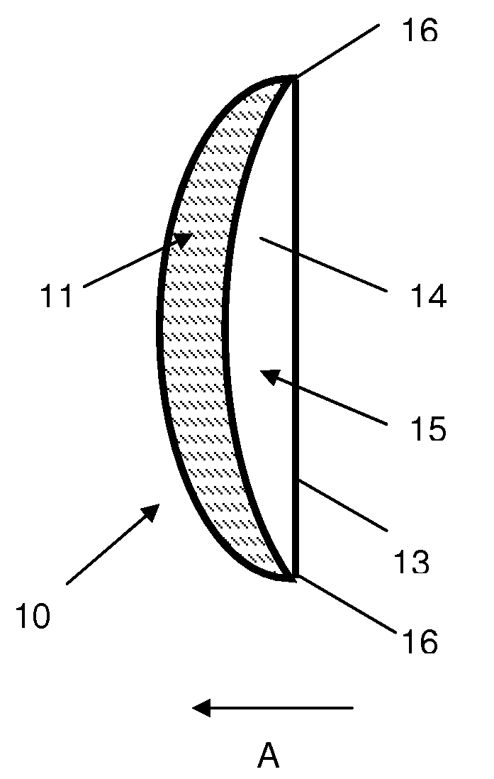
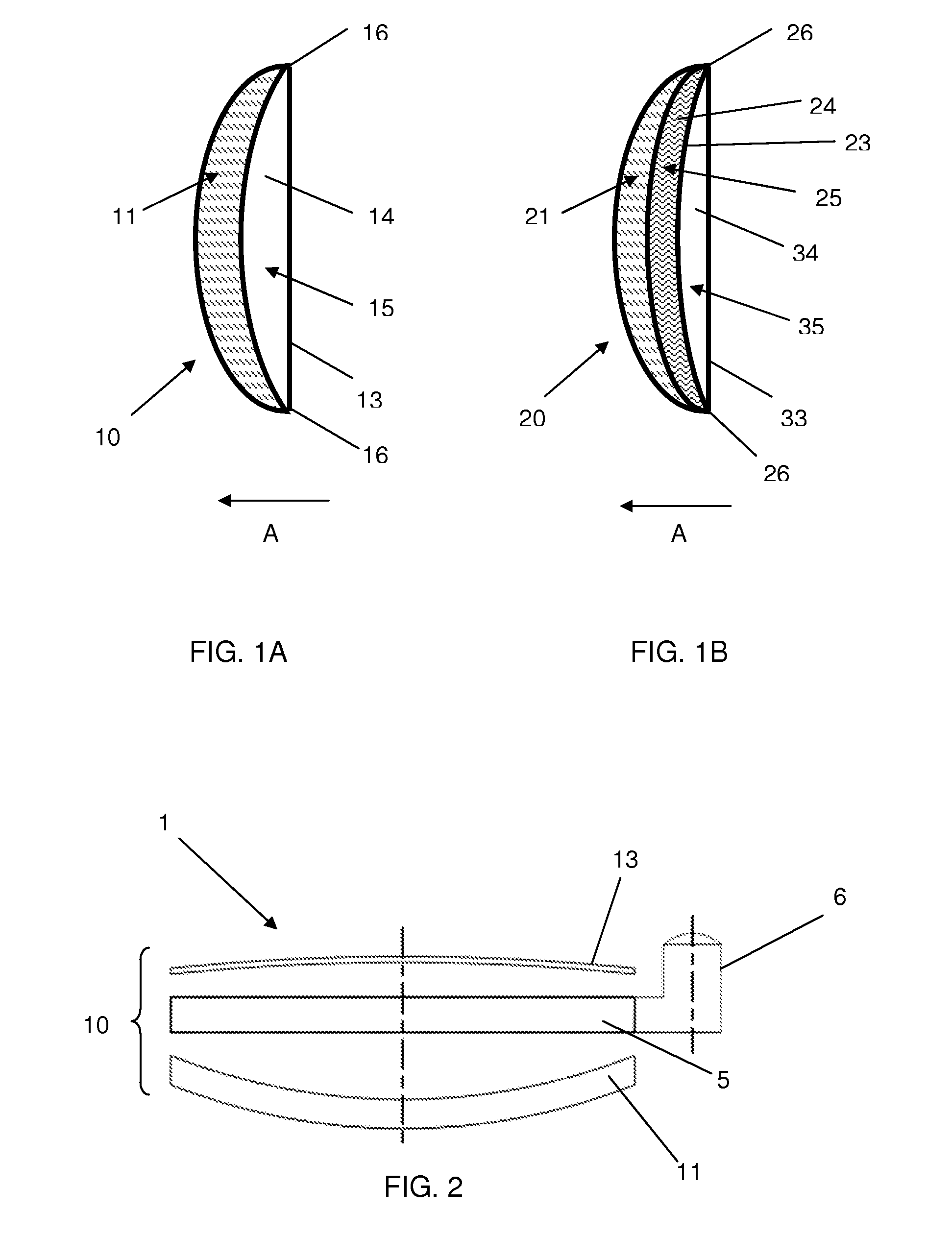
[0024]FIG. 1A shows a cross-sectional view of a first preferred embodiment of the optical apparatus, in the form of a variable focus lens 10, through which a wearer peers in the direction of arrow A. Lens 10 is a composite of two optic components, an anterior (i.e., front, with respect to the wearer) optic 11 that is substantially rigid and a posterior (i.e., back, with respect to the wearer) optic 15 that is a liquid.

[0025]Anterior optic 11 is a substantially rigid lens preferably made of a rigid, transparent substrate, such as a clear plastic or poly carbonate, glass plate, transparent crystal plate, or a transparent rigid polymer, for example, Polycarbonate of Bisphenol A or CR-39 (Diethylene glycol bisallyl carbonate). Anterior optic 11 may be made of an impact resistant polymer and...


PUM

PropertyMeasurementUnit
thicknessaaaaaaaaaa
thicknessaaaaaaaaaa
thicknessaaaaaaaaaa

Abstract

A variable focus lens apparatus includes at least one rigid optical disc, at least one flexible optical membrane and at least one layer of a transparent fluid that is in communication with a fluid channel and a reservoir. When incorporated in a spectacle lens, the lens system enables wearers to adjust the power of each lens individually, so as to achieve the preferred binocular visual performance, consistent with maximum stereopsis and binocular fusion at any desired object plane.

Description

FIELD OF THE INVENTION[0001]The present invention relates to the field of variable focus lenses, and more particularly to consumer ophthalmic lenses that are at least in part fluid- or liquid-filled.BACKGROUND OF THE INVENTION[0002]It is known that the ability of the human eye to accommodate, i.e., to alter the focal length of the natural lens in the eye, is gradually diminished with increased age. Accommodation in human beings is reduced to 3D (diopters) or less at an age range of 35-45 years. At that point, reading glasses or some other form of near vision correction becomes necessary for the human eye to be able to bring near objects (such as lines of text in a book or a magazine) to focus. With further aging, accommodation drops below 2D, and at that point visual correction when working on a computer or when performing some visual task at intermediate distances is needed.[0003]For best results and for best visual comfort, it is necessary to bring each eye to focus on the same vi...

Claims


Application Information

Patent Timeline
Patent Type & Authority Applications(United States)
IPC IPC(8): G02C7/02G02B3/14
CPCG02C7/085G02B3/14G02B1/14G02B1/11G02B3/02G02C2202/16
Inventor GUPTA, AMITAVAHAROUD, KARIMSCHNELL, URBAN
Owner ADLENS BEACON INC
Why Eureka
Try Eureka