Surface light source and liquid crystal display device using the same

A surface light source and light source technology, applied in the direction of light source, slender light source, lighting device, etc.

Inactive Publication Date: 2009-12-16
TORAY IND INC +1
View PDF4 Cites 16 Cited by
  • Summary
  • Abstract
  • Description
  • Claims
  • Application Information

AI Technical Summary

Problems solved by technology

However, in such a surface light source

Method used


Image

  • Surface light source and liquid crystal display device using the same
  • Surface light source and liquid crystal display device using the same
  • Surface light source and liquid crystal display device using the same

Examples


Embodiment 1-1

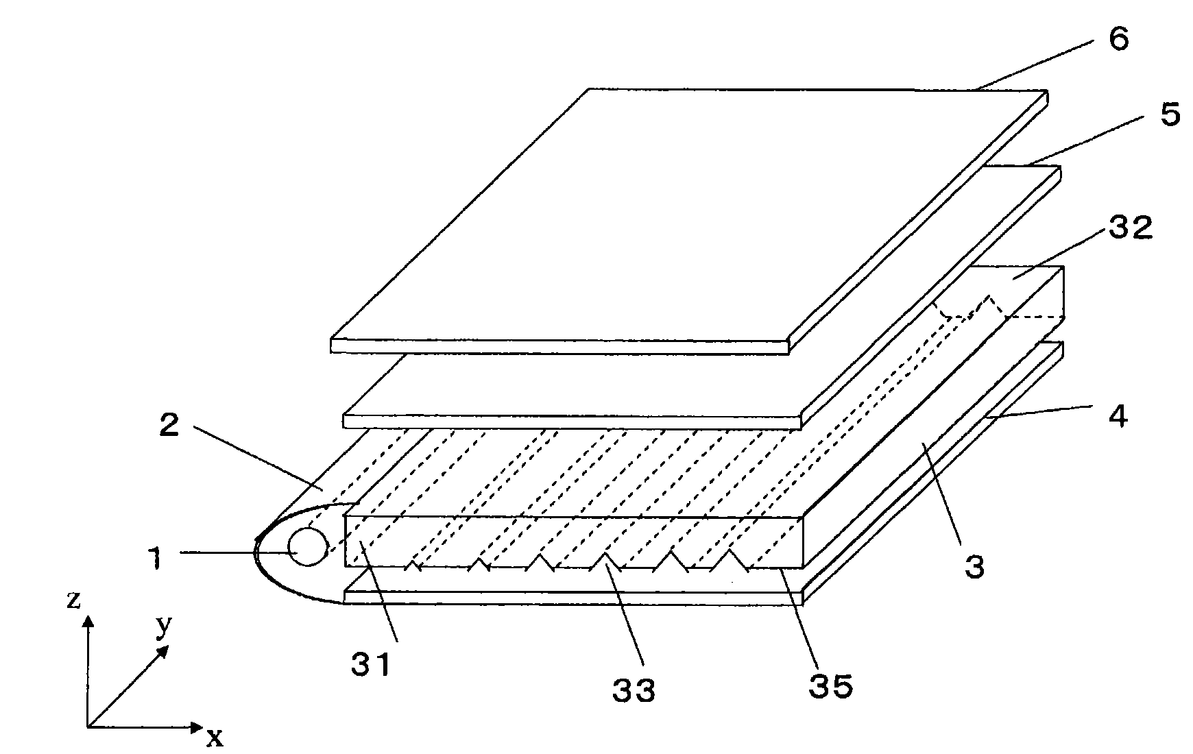
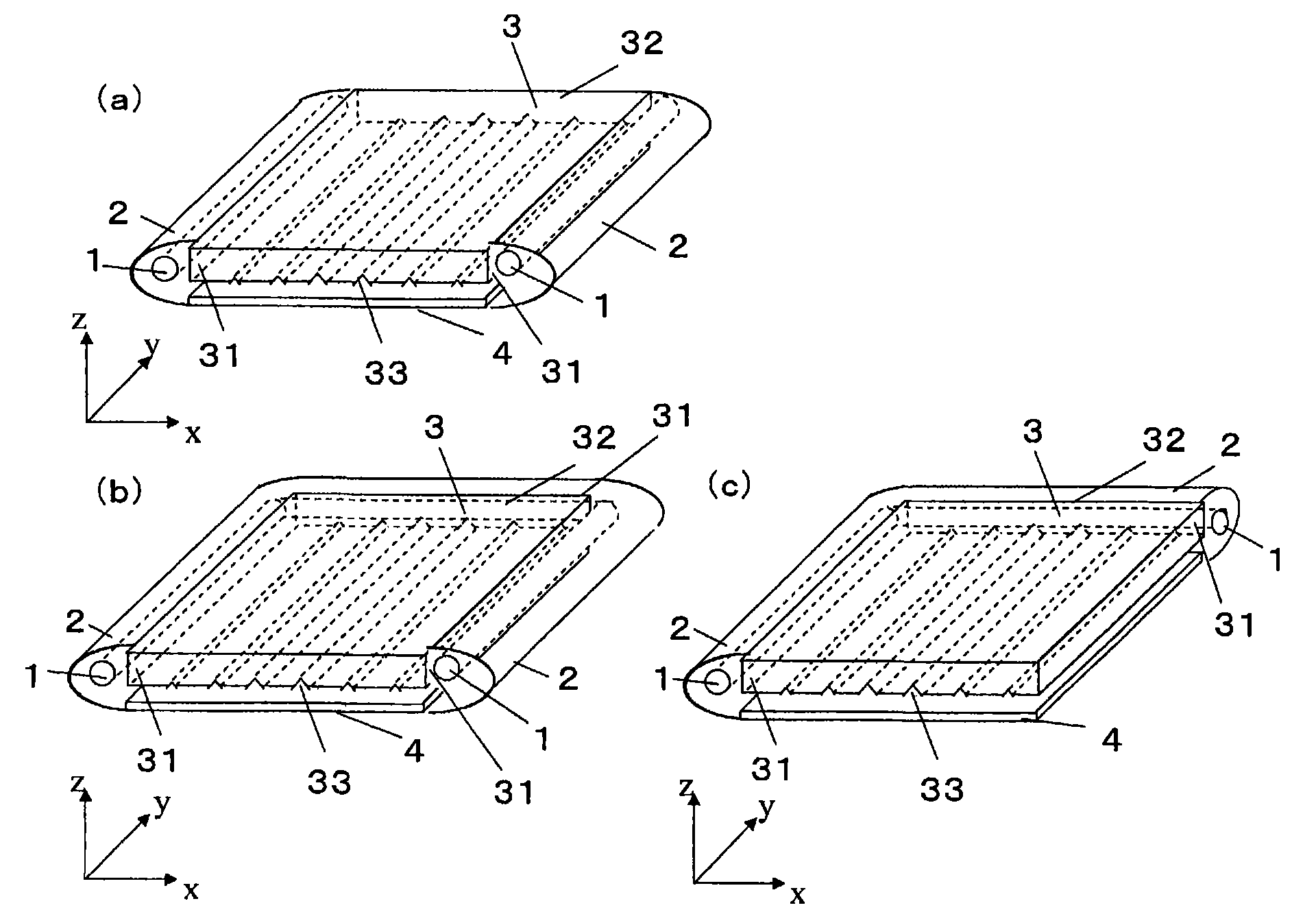
[0368] The light guide A-1 is installed in such a way that the surface without linear grooves is on the observer side, and two cold cathode fluorescent lamps (hereinafter referred to as CCFLs) are respectively installed on the two opposite light incident surfaces. "Lumiraichi" E6SV (manufactured by Toray Co., Ltd.) is installed around as a reflector. On the non-observer side of the light guide 3, a reflective sheet "Lumira" E6SL (manufactured by Toray Co., Ltd.) is provided. On the viewer side of the light guide 3, B-1 is used as the first optical film so that the direction in which the anisotropic diffusivity becomes the largest is parallel to the longitudinal direction of the linear groove of the light guide 3 (that is, θ5=0 °) configuration. C-1 is used as the second optical film on the first optical film B-1 so that its prism length direction is parallel to the direction in which the anisotropic diffusivity of the optical film B-1 becomes maximum (that is, θ6=0°). Mode s...

Embodiment 1-2

[0371] Except having used B-2 as a 1st optical film, it carried out similarly to Example 1-1, and produced the surface light source.

[0372] After lighting for 10 minutes, measure the brightness of 25 points in the surface light source (refer to Figure 18 (a)), it was found that the central brightness is 6950cd / m 2 (Evaluation A), the uniformity U was 81% (Evaluation A), and it was found that the center brightness and the uniformity U were good. In addition, the emission angle distribution from the central part of the surface light source was measured, and the viewing angle was found to be 30° in the vertical direction (evaluation A) and 45° in the horizontal direction (evaluation A), showing good viewing angle characteristics (see Table 4).

Embodiment 1-3

[0374] Except having used B-3 as a 1st optical film, it carried out similarly to Example 1-1, and produced the surface light source.

[0375] After lighting for 10 minutes, measure the brightness of 25 points in the surface light source (refer to Figure 18 (a)), it was found that the central brightness is 6690cd / m 2 (Evaluation C), the uniformity U was 85% (Evaluation A), and it was found that the center brightness and the uniformity U were good. In addition, the emission angle distribution from the center of the surface light source was measured, and the viewing angle was found to be 32° in the vertical direction (evaluation A) and 47° in the horizontal direction (evaluation A), showing good viewing angle characteristics (see Table 4).


PUM

PropertyMeasurementUnit
Top angleaaaaaaaaaa
Center brightnessaaaaaaaaaa

Abstract

Provided is a side light type surface light source, which has a high light use efficiency, a high luminance and a wide view angle. A liquid crystal display device using such light source is also provided. The surface light source is provided with a light source; a light guide body having at least one light incoming surface facing the light source and a light outgoing surface substantially orthogonally intersecting with the light incoming surface; and a first optical film arranged to face the light outputting surface. On the light guide body, a plurality of linear grooves or linear protruding sections are arranged substantially parallel on the light outputting surface or on the rear surface of the light outputting surface not outputting light. The first optical film has anisotropic diffusion characteristics, and is arranged to have a direction, in which the anisotropic diffusion is maximum, substantially parallel to the longitudinal direction of the linear grooves or the linear protruding sections.

Description

technical field [0001] The present invention relates to a surface light source for illuminating a liquid crystal display element or the like from the back surface, and a liquid crystal display device equipped with the surface light source. Background technique [0002] As a display device such as a personal computer, a television, or a mobile phone, a display using a liquid crystal is often used. These liquid crystal display elements themselves are not light emitters. Therefore, display is performed by irradiating light to the liquid crystal display element from the inner side using a surface light source. [0003] As the surface light source, there are a direct type in which a plurality of light sources are arranged directly under a liquid crystal display element, and an edge light type in which a light source is arranged to face the side end surface of the light guide. The direct type is mainly used in televisions, and the edge light type has the advantage of being small...

Claims


Application Information

Patent Timeline
IPC IPC(8): F21V8/00F21V5/00G02B5/02G02B6/00G02F1/13357F21Y103/00G02F1/1335
CPCG02B5/0257G02B6/0036G02B5/0242G02B6/0038G02B5/0278G02B5/0221G02B5/0231G02B5/0226G02F1/133524
Inventor 青山滋高桥弘造村井大士
Owner TORAY IND INC
Why Eureka
Try Eureka