Liquid crystal display device

A technology of liquid crystal display device and liquid crystal display panel, which is applied in the directions of instruments, light guides, optics, etc., can solve the problems of low heat dissipation, tilting of LED lamps 104, affecting the luminous effect, etc., and achieves good heat dissipation effect, stable installation, and simple structure. Effect

Inactive Publication Date: 2014-03-26
TCL CHINA STAR OPTOELECTRONICS TECH CO LTD
View PDF3 Cites 19 Cited by
  • Summary
  • Abstract
  • Description
  • Claims
  • Application Information

AI Technical Summary

Problems solved by technology

[0004] However, although the liquid crystal display device with this structure can realize a narrow frame, the heat dissipation of the LED lamp 104 in the backlight source 100 is a problem that cannot be ignored. Because only the bottom of the LED lamp 104 contacts the printed circuit board 102, its back directly against On the plastic frame 300, the plastic frame 300 is generally made of plastic material, and the heat dissipation is not high. Therefore, the heat generated by the LED lamp 104 will be extremely difficult to dissipate, and the LED lamp 104 will be easily damaged if used for a long time, reducing the temperature of the LED lamp. 104, and installing the LED lamp 104 by punching will easily tilt the LED lamp 104, causing poor contact of the LED lamp 104, affecting the luminous effect, and reducing the quality of the liquid crystal display device

Method used


Image

  • Liquid crystal display device
  • Liquid crystal display device
  • Liquid crystal display device

Examples


Embodiment Construction

[0023] In order to further illustrate the technical means adopted by the present invention and its effects, the following describes in detail in conjunction with preferred embodiments of the present invention and accompanying drawings.

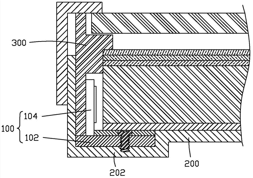
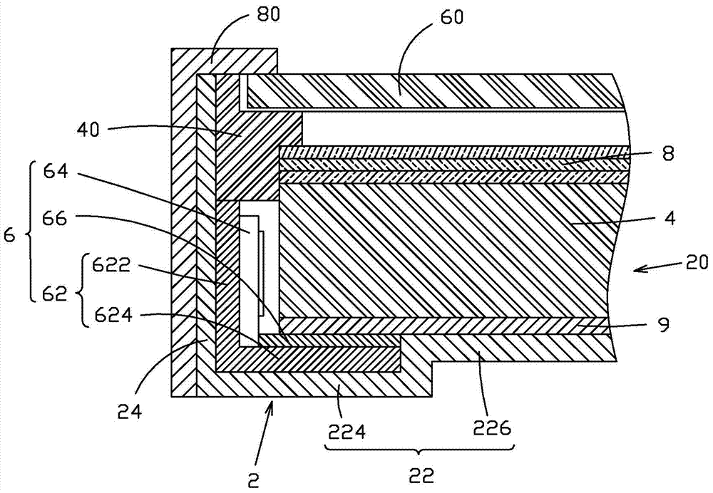
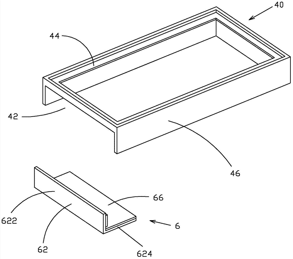
[0024] see figure 2 and image 3 , the present invention provides a kind of liquid crystal display device, and its structure is simple, specifically comprises: backlight module 20, the plastic frame 40 that is arranged on the top of backlight module 20, the liquid crystal display panel 60 that is installed in the plastic frame 40 and is installed in the liquid crystal display The front frame 80 on the panel 60, the backlight module 20 includes a backplane 2, a light guide plate 4 disposed in the backplane 2, a backlight source 6 disposed in the backplane 2, and an optical film disposed on the light guide plate 4 Sheet group 8, the backlight 6 includes a printed circuit board 62 and several LED lamps 64 installed and electrically connected to...


PUM


Abstract

The invention provides a liquid crystal display device. The liquid crystal display device comprises a backlight module (20), a rubber frame (40) arranged above the backlight module (20), a liquid crystal display panel (60) installed in the rubber frame (40) and a front frame (80) installed on the liquid crystal display panel (60), wherein the backlight module (20) comprises a backboard (2), a light guide panel (4) arranged in the backboard (2), a backlight source (6) arranged in the backboard (2) and an optical membrane set (8) arranged on the light guide panel (4); the backlight source (6) comprises a printed circuit board (62) and a plurality of LED lamps (64) which are installed and electrically connected to the printed circuit board (62); the printed circuit board (62) comprises a side portion (622) and a bottom (624) vertically connected to the side portion (622); the rubber frame (40) is provided with an opening groove (42) corresponding to the backlight source (6); the side portion (622) of the printed circuit board (62) is contained in the opening groove (42).

Description

technical field [0001] The invention relates to the field of liquid crystal display, in particular to a liquid crystal display device. Background technique [0002] A liquid crystal display (Liquid Crystal Display, LCD) has many advantages such as a thin body, power saving, and no radiation, and has been widely used. Most of the liquid crystal display devices currently on the market are backlight liquid crystal display devices, which include a liquid crystal display panel and a backlight module. The working principle of the liquid crystal display panel is to place liquid crystal molecules between two parallel glass substrates. There are many vertical and horizontal small wires between the two glass substrates. The direction of the liquid crystal molecules is controlled by electrifying or not, and the light of the backlight module Refracted out to produce a picture. Since the liquid crystal display panel itself does not emit light, the light source provided by the backlight...

Claims


Application Information

Patent Timeline
Patent Type & Authority Applications(China)
IPC IPC(8): G02F1/13357G02F1/13
CPCG02F1/1336G02F1/133615G02F1/133308G02F1/133317G02F1/13332G02F1/133314G02B6/0083G02B6/0073G02B6/0068G02B6/0085
Inventor 俞刚
Owner TCL CHINA STAR OPTOELECTRONICS TECH CO LTD
Why Eureka
Try Eureka