Head suspension
a head suspension and suspension technology, applied in the field of head suspensions, can solve the problems of complicated manufacturing processes, difficult to ensure assembly accuracy, and complicated structure, and achieve the effect of improving the assembling accuracy of the head suspension and simplifying the manufacturing process
- Summary
- Abstract
- Description
- Claims
- Application Information
AI Technical Summary
Benefits of technology
Problems solved by technology
Method used
Image
Examples
embodiment 1
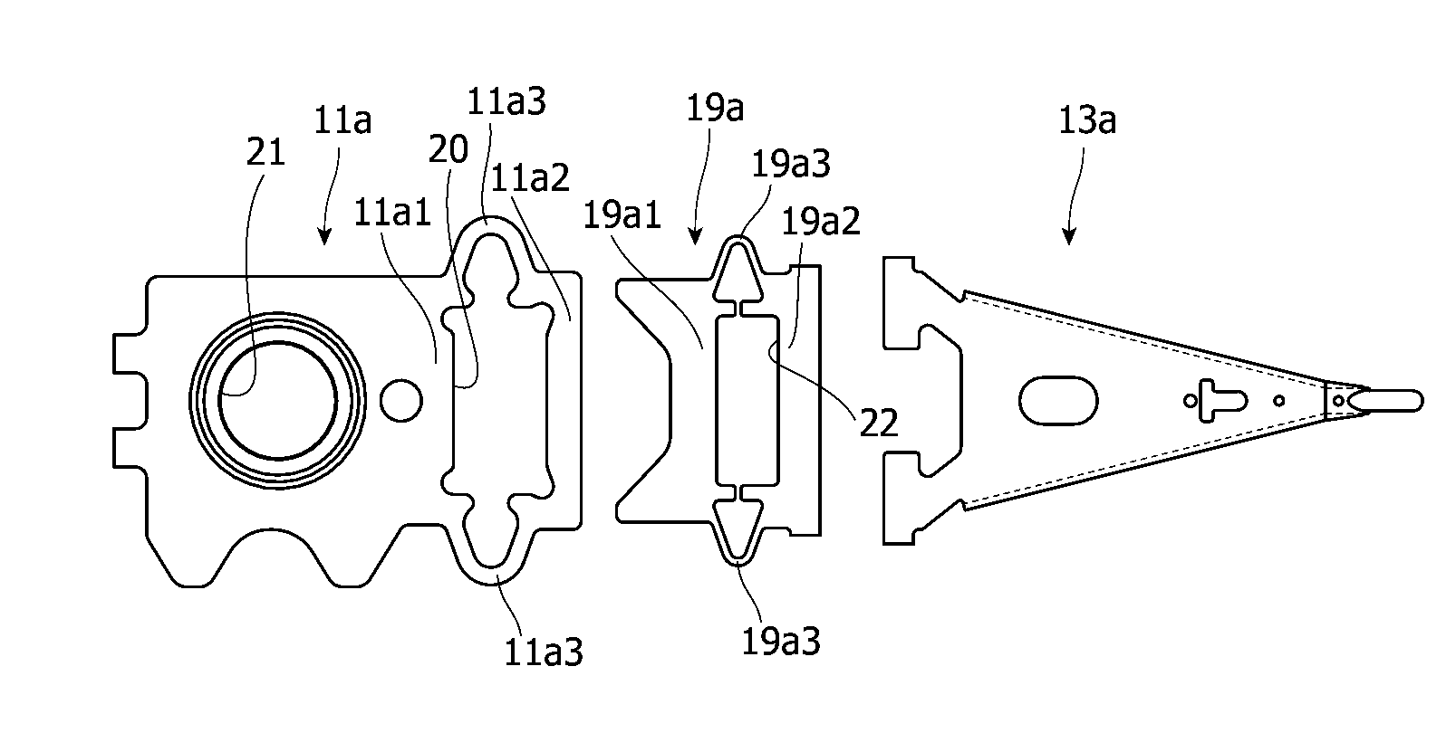
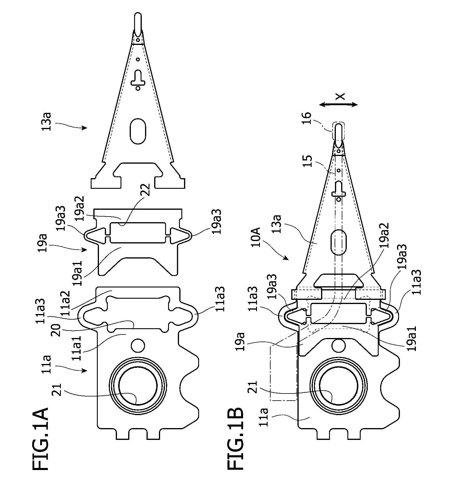
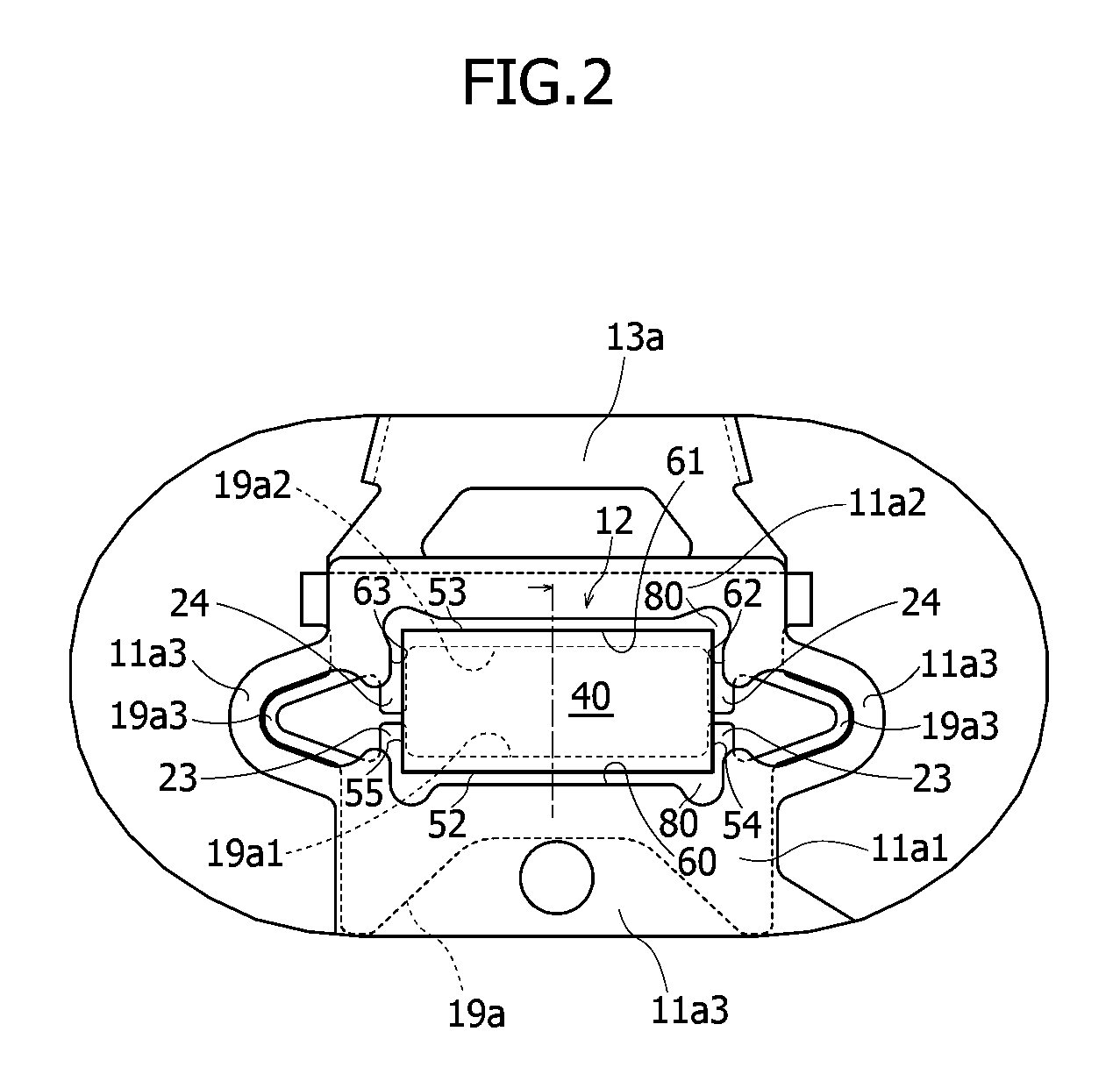
[0025]First, a head suspension will be explained with reference to FIGS. 1A to 3 in which FIG. 1A illustrates essential parts of the head suspension, FIG. 1B illustrates the head suspension, FIG. 2 is an enlarged top view illustrating a part around a piezoelectric element of the head suspension, and FIG. 3 is a sectional view taken along a line of FIG. 2.
[0026]In the following explanation, a base plate side of the head suspension is referred to as a base end or a rear end and a load beam side thereof is referred to as a front end or a front side. A surface side of the head suspension is a side opposite to a side where a magnetic disk is arranged and a back or bottom side of the head suspension is the side where a magnetic disk is arranged.
[0027]The head suspension 10A according to Embodiment 1 has a base plate 11a, a load beam 13a, a support member 19a, and a piezoelectric actuator 12.
[0028]The piezoelectric actuator 12 consists of a piezoelectric ceramic element (hereinafter refer...
embodiment 2
[0070]A head suspension will be explained in detail with reference to FIGS. 4A, 4B, and 5 in which FIG. 4A illustrates essential parts of the head suspension, FIG. 4B illustrates the head suspension, and FIG. 5 is an enlarged top view illustrating a part around a piezoelectric element of the head suspension.
[0071]The head suspension 10B of Embodiment 2 is basically the same as the head suspension 10A of Embodiment 1 except the configuration of a support member, and therefore, the parts common to the two embodiments are represented with the same reference marks to omit overlapped explanations.
[0072]In Embodiment 1, a part related to, for example, the base plate 11a is represented with “11a” plus a numeral. Like this, in Embodiment 2, a part related to, for example, a base plate 11b is represented with “11b” plus a numeral. This style of expression is to easily distinguish the different embodiments from each other.
[0073]Parts having similar reference marks such as the base end part “...
embodiment 3
[0083]A head suspension will be explained in detail with reference to FIGS. 6A, 6B, and 7 in which FIG. 6A illustrates essential parts of the head suspension, FIG. 6B illustrates the head suspension, and FIG. 7 is an enlarged top view illustrating a part around a piezoelectric element of the head suspension.
[0084]The head suspension 10C of Embodiment 3 is basically the same as the head suspension 10B of Embodiment 2 except the configuration of a support member, and therefore, the parts common to the two embodiments are represented with the same reference marks to omit overlapped explanations. Mainly explained hereunder is a difference between Embodiments 2 and 3.
[0085]According to Embodiment 2, the base end support 13b1 and front end support 13b2 of the support member 25 are connected to each other with the support links 13b3 outside the piezoelectric element 40.
[0086]According to Embodiment 3, a support member 27 of the head suspension 10C has a base end support 13c1, a front end ...
PUM
| Property | Measurement | Unit |
|---|---|---|
| thickness | aaaaa | aaaaa |
| thickness | aaaaa | aaaaa |
| thickness | aaaaa | aaaaa |
Abstract
Description
Claims
Application Information
 - R&D
- Intellectual Property
- Life Sciences
- Materials
- Tech Scout
- Unparalleled Data Quality
- Higher Quality Content
- 60% Fewer Hallucinations
Browse by: Latest US Patents, China's latest patents, Technical Efficacy Thesaurus, Application Domain, Technology Topic, Popular Technical Reports.
© 2025 PatSnap. All rights reserved.Legal|Privacy policy|Modern Slavery Act Transparency Statement|Sitemap|About US| Contact US: help@patsnap.com


