Adhesive application apparatus and bookbinding apparatus

Active Publication Date: 2010-08-19
NISCA KK
View PDF5 Cites 18 Cited by
  • Summary
  • Abstract
  • Description
  • Claims
  • Application Information

AI Technical Summary

Benefits of technology

[0020]According to the present invention, the level adjusting means provided to the glue container is utilized to adjust a liquid amount in the coating layer formed on the surface of an application roller to increase or decrease in accordance with an application length and/or an application width of the adhesive applied to the sheet bundle, and hence the following effect is demonstrated. First, when each of a rotating speed and a moving speed of the application roller is set to an optimum value according to an application region of a widely used sheet bundle, efficient application processing can be performed. Furthermore, in case of an extremely large or extremely small sheet bundle size that the application region of the sheet bundle is different from the set value, since a liquid amount in the coating layer formed on the surface of the application roller is adjusted to increase or decrease, a predetermined application layer can be always obtained with respect to widespread sheet bundles. Therefore, an insufficient portion where a layer is thin is not produced in the length direction or the width direction of application layer, and hence page missing or a bookbinding quality is not affected.
[0021]Furthermore, according to the present invention, when adjusting a liquid amount in the coating layer formed on the surface of

Problems solved by technology

Therefore, an insufficient portion where a layer is thin is not produced in the length direction or the

Method used


Image

  • Adhesive application apparatus and bookbinding apparatus
  • Adhesive application apparatus and bookbinding apparatus
  • Adhesive application apparatus and bookbinding apparatus

Examples


embodiment 1

[0066]In the configuration described in conjunction with FIG. 3, the later-described control CPU 60 executes a bookbinding operation by a program (not shown) stored in an ROM. In this process, the applying operation controlling means 66 includes size recognizing means 66S and the application region comparing means 66P. The size recognizing means 66S acquires a sheet size (which is precisely a length Ls of a spine) of a sheet bundle to which the adhesive is applied and bundle thickness (Lt) information of the sheet bundle. In the configuration of the later-described bookbinding apparatus A, the length Ls of the spine is acquired from sheet size information from an image forming apparatus C, and the bundle thickness Lt information of the sheet bundle is obtained from a detection signal from later-described bundle thickness detecting means (not shown). In this manner, the size identification of the sheet bundle to which the adhesive is applied can be acquired from a size of a utilized ...

embodiment 2

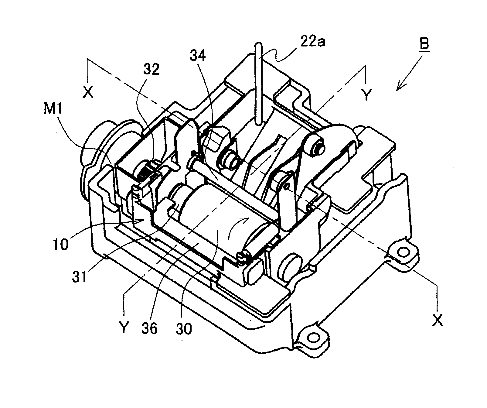
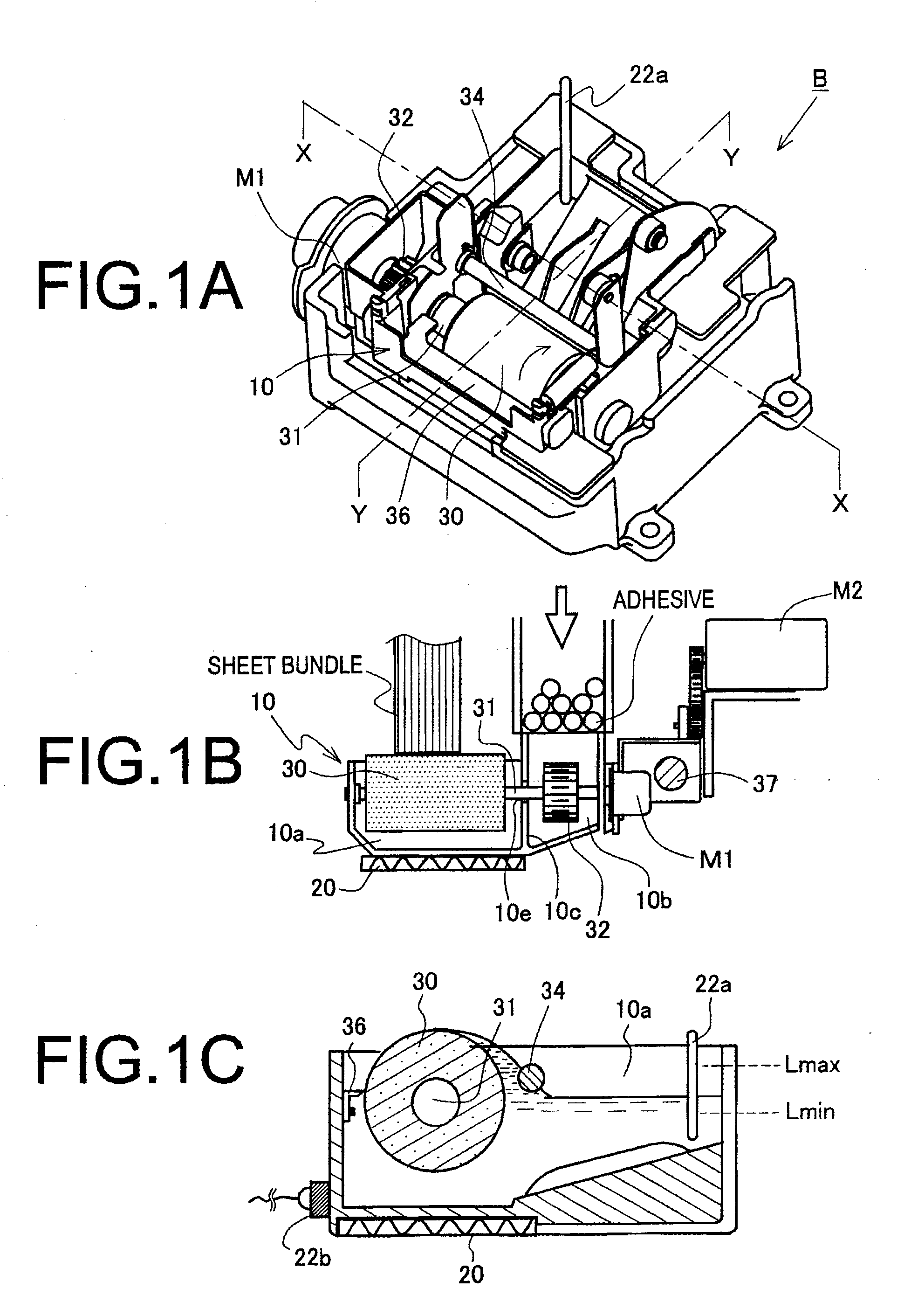
[0072]Embodiment 2 will now be described. As shown in FIGS. 5A to 5C, the above-described application roller 30 is rotatably disposed in an accommodating chamber 10a of a glue container 10. An adhesive in an adhesive application layer SL is refluxed in the accommodating chamber 10a while adhering to an outer periphery of a roll along a rotating direction of this application roller 30. A reflux amount restricting member 34 is provided on a downstream side of a rotating direction of this application roller outer periphery. A predetermined gap L is provided between this reflux amount restricting member 34 and the application roller surface. An adhesive amount in the adhesive application layer SL is small when this gap L is large, and an adhesive amount in the adhesive application layer SL is large when the gap L is small. Therefore, the reflux amount restricting member 34 is supported so as to be movable in the glue container 10, e.g., so as to movable through a long hole bearing 40. T...

embodiment 3

[0075]Embodiment 3 will now be explained. As shown in FIGS. 6A to 6C, this Embodiment 3 is configured to increase or decrease a liquid surface level re of an adhesive by changing an adhesive accommodation capacity of an accommodating chamber 10a. Therefore, an accommodated liquid capacity adjusting member 51 is arranged in a liquid accommodating chamber 10a of a glue container 10. This accommodated liquid capacity adjusting member 51 is arranged like a float in a liquid in the accommodating chamber 10a of the glue container 10, and the liquid surface level re is increased from a liquid surface level re1 in FIG. 6A to a liquid surface level re2 in FIG. 6B when this member is immersed in the liquid.

[0076]An occupied position shifting means 52 is provided to the accommodated liquid capacity adjusting member (which is referred to as a float member) 51. This occupied position shifting means 52 includes a support lever 52x that suspends the float member 51 in the accommodating chamber 10a...


PUM

PropertyMeasurementUnit
Lengthaaaaaaaaaa
Timeaaaaaaaaaa
Widthaaaaaaaaaa

Abstract

The present invention provides an adhesive application apparatus that can form a uniform application layer when applying an adhesive to an end face of a sheet bundle by an application roller even though a length or a width of the sheet bundle is not less than or not greater than a predetermined size, and a liquid amount in an immersed coating layer formed between the surface of the application roller and the application surface of the sheet bundle can be adjusted by increasing or decreasing based on an application length and/or an application width of the sheet bundle. Therefore, level adjusting means for adjusting a liquid surface level in an equipped accommodating chamber including an application roller to increase or decrease is provided in a glue container. This level adjusting means increases the liquid surface level above a predetermined value by resupplying a solid adhesive to the glue container, or is configured to enable adjusting a position of a reflux amount restricting member that restricts (stems) an adhesive amount refluxed along the surface of an application roller, or configured to enable moving an occupied position of an accommodated liquid capacity adjusting member that adjusts an allowable accommodation amount of the adhesive in the accommodating chamber.

Description

BACKGROUND OF THE INVENTION[0001]1. Field of the Invention[0002]The present invention relates to an adhesive application apparatus in a bookbinding apparatus and the bookbinding apparatus using this adhesive application apparatus and to an improvement in an adhesive application mechanism that applies a hot-melt adhesive to an end face of a back portion of a sheet bundle obtained by bundling as a copy.[0003]2. Description of the Related Art[0004]In general, this type of adhesive application apparatus is widely known as an apparatus that bundles sheets carried out from, e.g., an image forming apparatus as a copy, sets them at a predetermined adhesive applying position to be carried, provides a glue container that applies an adhesive on an end face of a back portion thereof, and performs immersion and application of an adhesive on an application roller arranged in this glue container. Further, a method for accommodating a hot melt (a hot-melt adhesive) in this glue container and contro...

Claims


Application Information

Patent Timeline
IPC IPC(8): B42C9/00B05C1/08
CPCB05C1/003B05C1/08B42C9/00B05C11/101B05C1/0813
Inventor SASAMOTO, SHINYATSUCHIYA, ATSUSHI
Owner NISCA KK
Why Eureka
Try Eureka