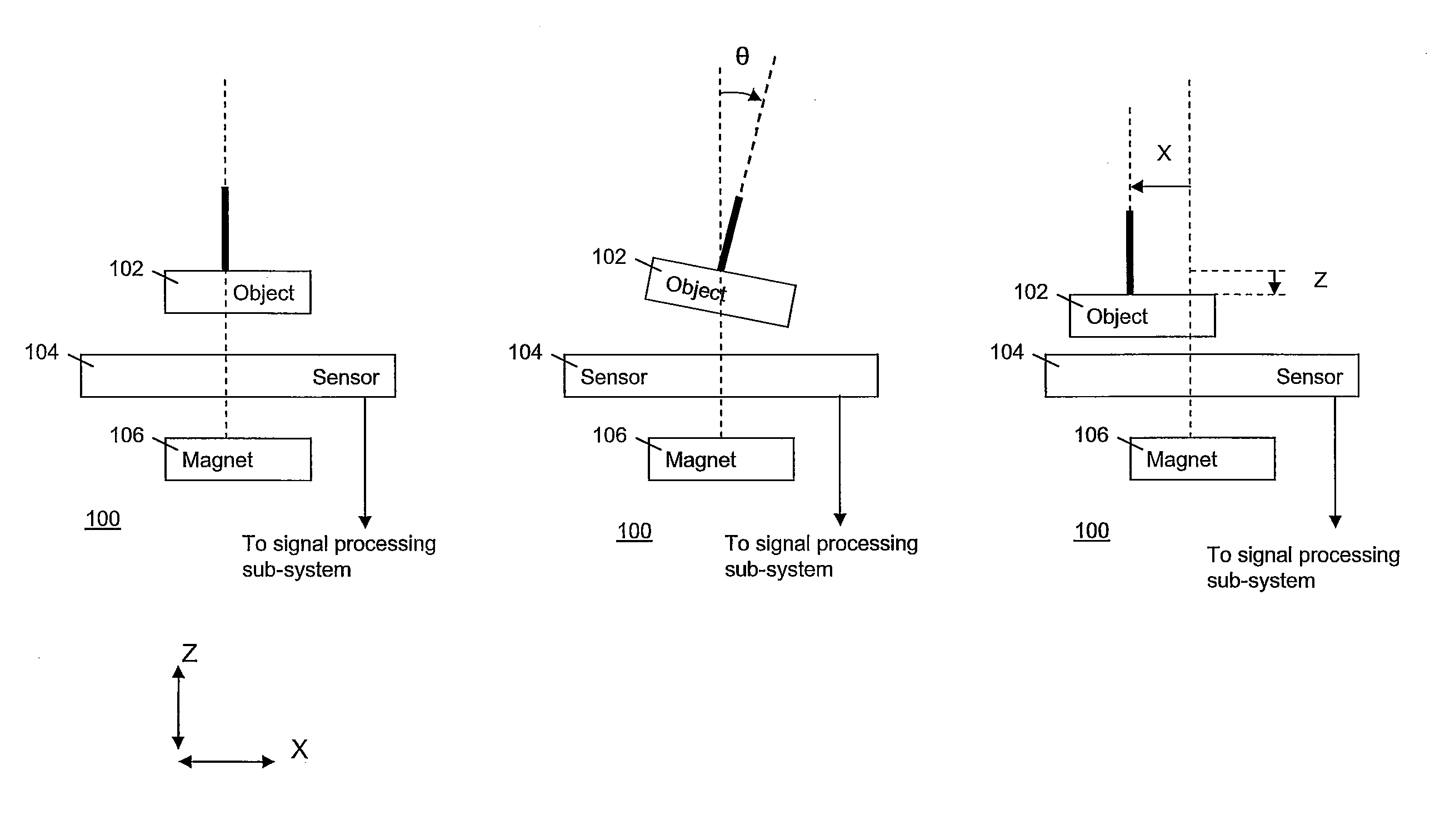
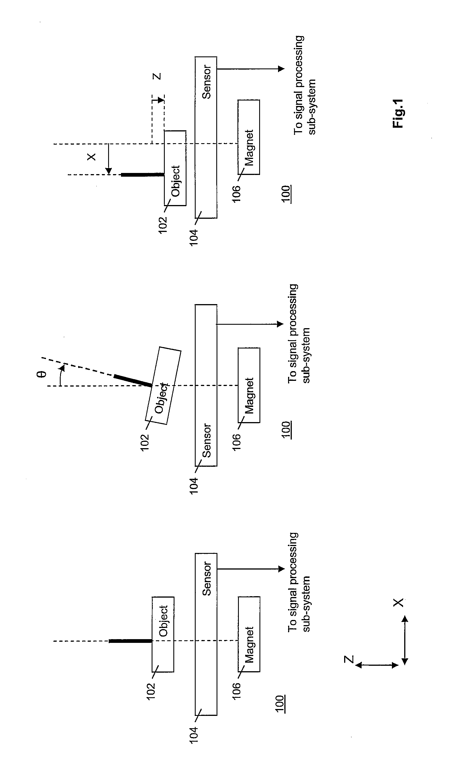
[0007]More specifically, the tilt sensitivity S of the joystick, typically expressed in mV / deg, depends on the distance between the joystick and the sensor and increases if this distance is shortened. In the case of an ideal joystick, the output Vout=S·θ is zero Volts if the tilt angle θ equals zero degrees, and the output remains zero if the distance between joystick and sensor is changed. However, in a manufacturing process, it will be very difficult to make such an ideal joystick. This would require a perfect parallel alignment of the magnetic plate at the bottom of the joystick to the sensor die. Due to tolerances in the suspension of the joystick, in the glued connections, the
machining of parts, etc. there will always be a slight misalignment. This misalignment induces a certain tilt-offset, θoffset, of the magnetic plate with respect to the sensor die. This implies that, even if the joystick is not touched (θ=0), a small tilt angle is present and subsequently the output signal of the sensor will be non-zero, Vout=S·(θ-θoffset). The sensitivity of the output signal to the tilt-angle is a function of the distance z between the joystick and the sensor die, S(z). Therefore, if the distance between the joystick and the sensor die changes, the sensitivity changes and, as a result, the output signal also changes. Pressing the joystick in the Z-direction therefore causes an output signal which the
laptop or
mobile phone interprets as a certain tilt of the joystick. This is an undesired effect because pressing the joystick in the Z-direction now moves or accelerates the cursor or pointer on the display screen.
[0009]One of the solutions to this problem is keeping the cursor in its position when the Z-signal changes rapidly. A rapid change in the Z-signal is then interpreted as a pressing action. This solution requires that the current values of the coordinates or of other parameters of the pointer be stored. If the Z-signal changes rapidly, the pointer coordinates or other parameters (e.g., speed) are kept as stored so that the behavior of the pointer is not affected, e.g., the pointer does not move or is not accelerated when already moving as a result of the detected X-signal and Y-signal at the time of pressing. These signals are then ignored. When the Z-signal is only changing slowly, it is assumed that the pointer is allowed to move under combined control of the X-signal, the Y-signal and the Z-signal as generated by the sensor. This solution may introduce a small
delay between joystick movement and cursor movement, dependent on the implementation.
[0010]Another solution is using a calibration procedure to determine the tilt-angle offset and to calculate a new output signal for the sensor that reduces or eliminates the vertical movement of the joystick. This solution avoids the delays resulting from the first-mentioned approach.
[0012]The rationale for the invention is as follows. As mentioned above, the sensitivity S depends on the distance between the object and the
reference plane. For ease of illustration, the example is considered wherein the sensor is located in the
reference plane, but other configurations work as well, such as having the sensor integrated with the object. In order to have the value of the tilt signal equal zero in the object's
rest position and without the object's being tilted, the first quantity is subtracted from the current value. In order to have the thus corrected current value depend linearly on the tilting angle the second quantity is subtracted from the initially corrected value. The second quantity is the product of θoffset and the difference in the sensitivity in the
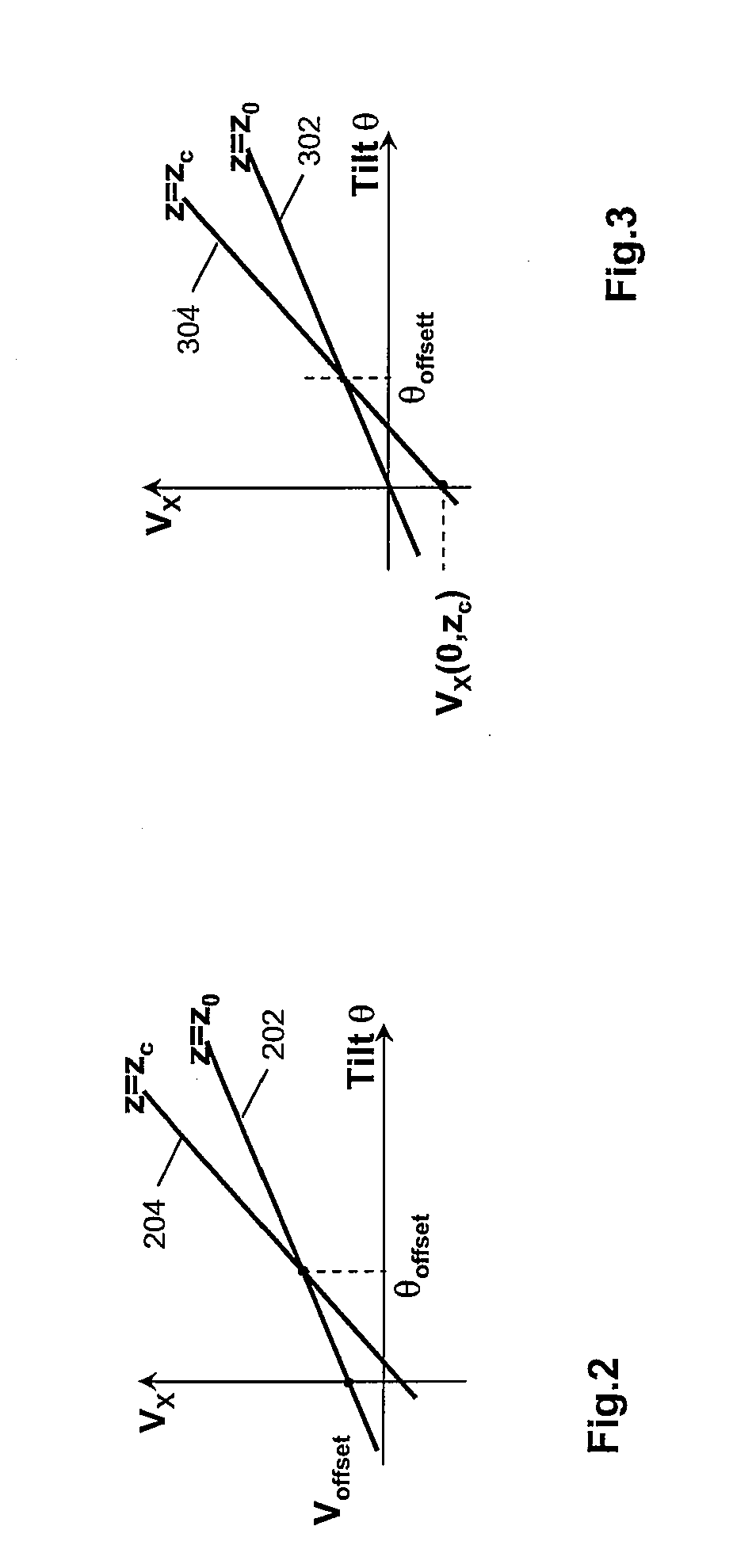
rest position and in the current position along the reference axis. The invention is based on the insight that in good approximation the distance signal is a linear function of the distance. This implies that a difference between sensitivity values at different distances can be expressed in differences of the distance signal measurements. Further, θoffset can be expressed as the ratio between, on the one hand, the value of the tilt signal if the angle is zero and the distance has a predetermined length, and the difference of the sensitivity values in the
rest position and the predetermined distance. As a result, the second quantity can be expressed entirely in signal values supplied by the sensor, so that the calibration process is simple.
[0015]In a further embodiment, the calibration means is further operative to scale the corrected value of the tilt signal by a factor. The factor is a further ratio of a third term and a fourth term. The third term is representative of a value of a sensitivity of the sensor when the object is in the rest position. The fourth term is representative of a value of the sensitivity of the sensor when the object is in a current position. The fourth term is, e.g., the current sensitivity value of the current sensitivity value raised to the power of “n”, wherein n may be larger than unity. In this further embodiment, the effect of the decreasing distance on the tilt signal is reduced, when the object is pressed and tilted.
[0016]The invention also relates to a calibration method for being carried out in a
signal processing system, and to
software with instructions to carry out such method. As to the latter, the invention can be commercially exploited in the form of providing
software, e.g., as an after-market add-on, to be installed in the
signal processing system with aforesaid object-sensor combination. The
signal processing system is comprised in, e.g., a
mobile device such as a mobile telephone or a
laptop PC, and the object comprises a joystick in the
user interface. The software is then installed at the
mobile device's
data processing system. As a result of the software, the user-friendliness of the
user interface is greatly improved in operational use of the software.

