Image processing apparatus, method of controlling the same, and storage medium

a technology of image processing and storage media, applied in the direction of program control, data processing applications, multi-programming arrangements, etc., can solve the problems of job flow that needs to be preformed only once to be executed, job flow that needs to be executed only once, and job flow that is limited

Inactive Publication Date: 2010-08-19
CANON KK
View PDF6 Cites 7 Cited by
  • Summary
  • Abstract
  • Description
  • Claims
  • Application Information

AI Technical Summary

Benefits of technology

[0020]The present invention provides an image processing apparatus that is capable of more reliably synchronizing an execution state of a job flow set in a plurality of machines without using a management server, a method of controlling the same, and a storage medium.

Problems solved by technology

Preserving the job flow setting that needs to be performed only once takes up memory space of a memory which is limited in storage capacity, and at the same time, poses a risk of mishandling the job flow, causing the job flow that needs to be preformed only once to be executed again.
Further, job flows the execution of which is limited to a predetermined number of times, not alone once, also suffer from the same problems.
However, in constructing a job flow system using the above-mentioned sever for job flow management, there are the following problems to be solved:
In this job flow system, synchronization is performed via the management server, and hence if the job flow is executed simultaneously by a plurality of digital multi-function peripherals, there is the risk of executing the process more than once, which is required to be executed only once.
As a result, during this time period, it is impossible to prevent any of the other digital multi-function peripherals from executing the job flow.
Further, the server is required to be provided for management of job flows, and hence it takes time and labor for the user to manage the server.
Nevertheless, if a digital multi-function peripheral is provided with a server function, the power needs to be constantly supplied to the digital multi-function peripheral, similarly to the server, resulting in degraded maintainability where the power cannot be casually turned off for maintenance.

Method used


Image

  • Image processing apparatus, method of controlling the same, and storage medium
  • Image processing apparatus, method of controlling the same, and storage medium
  • Image processing apparatus, method of controlling the same, and storage medium

Examples


Embodiment Construction

[0041]The present invention will now be described in detail below with reference to the accompanying drawings showing embodiments thereof.

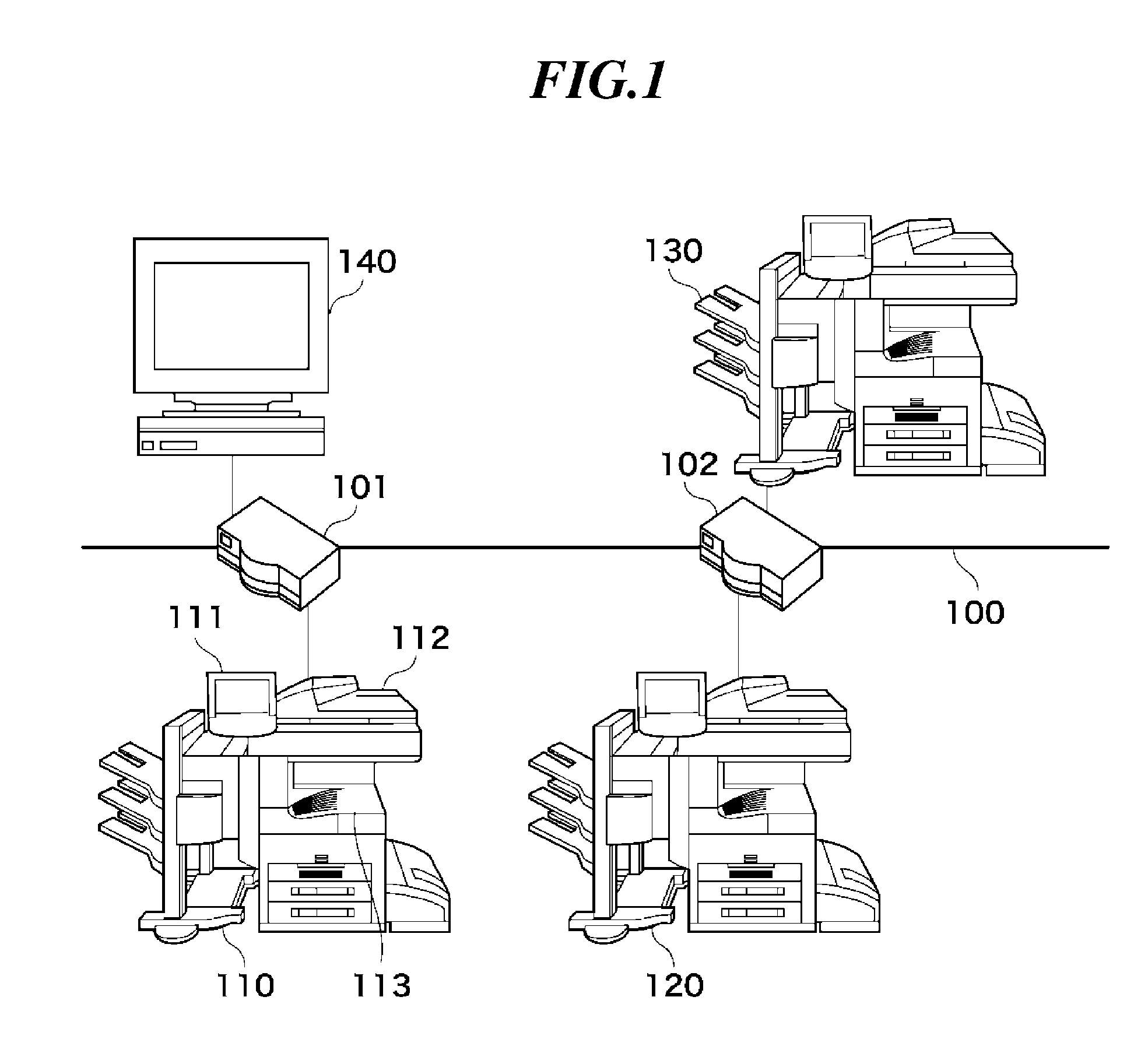
[0042]FIG. 1 is a view showing the overall configuration of a workflow system where digital multi-function peripherals as image processing apparatuses according to an embodiment of the present invention are connected to a network.

[0043]As shown in FIG. 1, digital multi-function peripherals 110, 120, and 130 (hereinafter represented by the digital multi-function peripheral 110 when deemed appropriate) are connected to a LAN 100 implemented e.g. by an Ethernet (registered trademark) via respective routers 101 and 102. In the system to which the image processing apparatus according to the present invention is applied, however, the number of connected apparatuses is by no means limited to three, i.e. the number of the illustrated ones.

[0044]Further, in the present embodiment, although the LAN is employed as connecting means, this is not limitative. Fo...


PUM


Abstract

An image processing apparatus that is capable of more reliably synchronizing an execution state of a job flow set in a plurality of machines without using a management server. In the digital multi-function peripheral, a job flow list management section receives a job flow setting file in which a job flow to be executed is described, and a job execution section executes the job flow based on the received job flow setting file. A communication section notifies other digital multi-function peripherals of execution of the job flow when the job flow is executed, and notifies the other digital multi-function peripherals of termination of the job flow when the execution of the job flow is terminated.

Description

BACKGROUND OF THE INVENTION[0001]1. Field of the Invention[0002]The present invention relates to an image processing apparatus, a method of controlling the same, and a storage medium, and more particularly to an image processing apparatus configured to execute a job flow and a method of controlling the same (job flow management method).[0003]2. Description of the Related Art[0004]In recent years, a digital multi-function peripheral (multi-function machine) has come into actual use which includes a digital copying machine, i.e. an example of an image processing apparatus, as a basic component and is equipped with a large number of additional functions.[0005]The digital multi-function peripheral is capable of performing facsimile communications using a scanner or a printer. The digital multi-function peripheral is also capable of developing code data sent from a computer into bitmap data and printing out the same using the printer.[0006]Further, the digital multi-function peripheral i...

Claims


Application Information

Patent Timeline
Patent Type & Authority Applications(United States)
IPC IPC(8): G06F9/46
CPCG06F3/1207G06F3/122G06F3/124G06F3/1259G06F3/1261G06Q10/06G06F3/1267G06F3/1274G06F3/1285G06F3/1291G06F9/5038G06F3/1262
Inventor ITO, FUMITOSHI
Owner CANON KK
Why Eureka
Try Eureka