Automatic cloth cutting mechanism

A cloth cutting mechanism and cloth cutting technology, applied to sewing machine components, sewing machine control devices, textiles and papermaking, etc., can solve the problems of troublesome assembly, complex structure, and low manufacturing cost, and achieve simple assembly, simple overall structure, and easy procurement convenient effect

Inactive Publication Date: 2017-05-31
BULLMER ELECTROMECHANICAL TECH
View PDF7 Cites 6 Cited by
  • Summary
  • Abstract
  • Description
  • Claims
  • Application Information

AI Technical Summary

Problems solved by technology

In this technical solution, the cutter is arranged under the platen, and the cutter and the cutter groove use the same rotating motor. Although the problem of synchronous rot

Method used


Image

  • Automatic cloth cutting mechanism
  • Automatic cloth cutting mechanism
  • Automatic cloth cutting mechanism

Examples


Example Embodiment

[0029] Example one

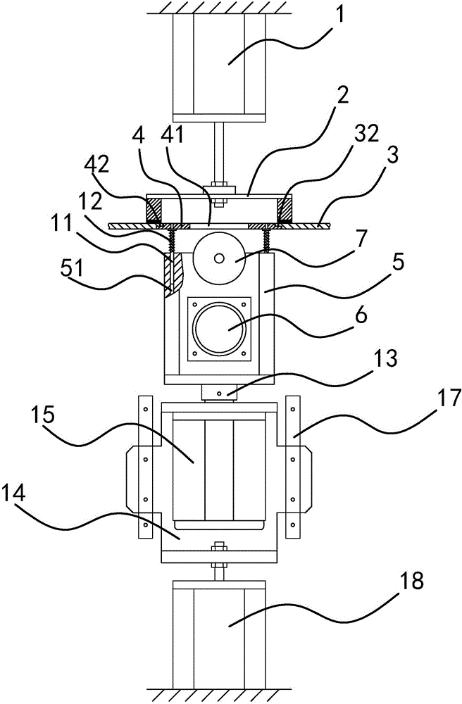
[0030] Such as figure 1 , 2 As shown in and 3, the automatic cloth cutting mechanism is installed on the sewing equipment. The sewing equipment is equipped with a controller, a platen 3 and a pressing assembly located above the platen 3. The pressing assembly includes a pressing plate 2 and a driving pressing plate. The second driving part of the plate 2 for pressing the cloth is connected to the controller. The second driving part is the pressing cylinder 1. Of course, the second driving part can be an electromagnet or other linear driving mechanism in addition to the pressing cylinder 1. The automatic cloth cutting mechanism is located under the table 3, and includes a cloth cutting motor seat 5, a rotating motor mounting seat 14, a driving part 1, and a cutting knife groove disc 4 with a strip through hole 41.

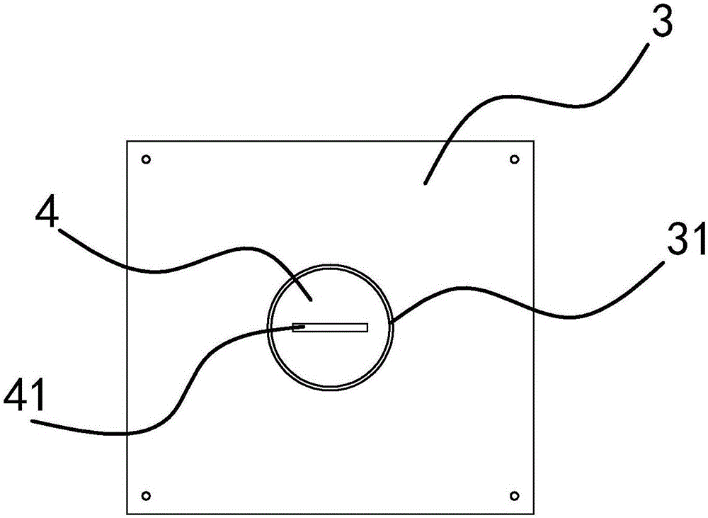
[0031] The platen 3 is provided with a circular mounting hole 31 that matches the cutter groove disc 4, the cutter groove disc 4 is located in the c...

Example Embodiment

[0040] Example two

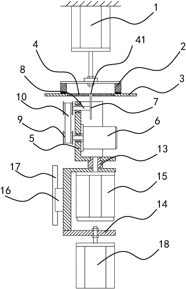
[0041] Such as Figure 5 As shown, the difference between this embodiment and the first embodiment is that the cutter assembly includes a straight knife cutter 28, a cutter shaft 26, a connecting rod 24, and an eccentric wheel 22 fixedly mounted on the output shaft of the cloth cutting motor. The upper end of the cloth cutting motor seat is provided with a guide groove 29. The lower end of the cutter shaft 26 is fixedly connected with a screw 25 and is located in the cloth cutting motor seat. The upper end of the connecting rod 24 is sleeved on the screw 25 and rotates around the screw 25. The lower end is sleeved on the eccentric wheel 22 through a needle bearing 23 and rotates around the eccentric wheel 22. The upper end of the cutter shaft 26 passes through the guide groove 29 and extends above the cutter motor seat. The straight knife cutter 28 passes through the cutter seat 27 It is fixedly connected to the upper end of the cutter shaft 26, and the stra...


PUM


Abstract

The invention provides an automatic cloth cutting mechanism and belongs to the technical field of sewing equipment. The problems that an existing cloth cutting mechanism is complex in structure and high in cost are solved. The automatic cloth cutting mechanism comprises a cloth cutting motor seat and a cutter groove disc, a cutter assembly with a cutter and a cloth cutting motor for driving the cutter assembly to work are arranged on the cloth cutting motor seat, and a first driving part and a rotary motor mounting seat connected with the first driving part are further included, and a cutter rotary motor is arranged on the rotary motor mounting seat. The cutter groove disc is connected with the cloth cutting motor seat through a transmission structure, an output shaft of the cutter rotary motor is fixedly connected with the cloth cutting motor seat and drives the cloth cutting motor seat and the cutter groove disc to rotate, and the first driving part drives the rotary motor mounting seat and the cloth cutting motor mounting seat to vertically move. The automatic cloth cutting mechanism has the advantages of achieving free curve cloth cutting and being simple in structure, good in stability and low in cost.

Description

technical field [0001] The invention belongs to the technical field of sewing equipment and relates to an automatic cloth cutting mechanism. Background technique [0002] Sewing is an important processing procedure for garments and hats. During the sewing process, multiple cuttings are carried out according to the needs. Not only can it be cut in a straight line, but because garments generally have arcs or bent parts with angles, it is important for cutting cloth The organization has put forward higher requirements, requiring it to also perform multi-angle cutting such as arcs or folded lines. [0003] In order to solve the above problems, a cloth cutting mechanism with a rotatable cutter came into being. Generally, three motors are provided, namely: the drive motor for the cutter to move up and down (or the cutter blade to rotate), the cutter rotating motor, and the cutter groove rotating motor. Since the cutter is installed on the platen, and at the same time, the cutter ...

Claims


Application Information

Patent Timeline
IPC IPC(8): D05B37/04D05B69/10
CPCD05B37/04D05B69/10D05D2305/08
Inventor 谭炜军
Owner BULLMER ELECTROMECHANICAL TECH
Why Eureka
Try Eureka