Assemblage of sealing nail

a technology of sealing nail and assemblage, which is applied in the direction of washing machines, ways, applications, etc., can solve the problems of reducing the operating efficiency, improperly extending the force of the nail, and reducing the sealing efficiency of the nail, so as to achieve smooth hammering operation and increase sealing efficiency

Inactive Publication Date: 2010-08-26
YU BO ZHANG
View PDF6 Cites 11 Cited by
  • Summary
  • Abstract
  • Description
  • Claims
  • Application Information

AI Technical Summary

Benefits of technology

[0011]It is an object of the present invention to provide an assemblage of sealing nail, which facilitates to increase the sealing efficiency between the nail and planking as well as attain a smooth hammering operation.

Problems solved by technology

Accordingly, the operation of inserting the conventional nail 12 inevitably renders the exhaustion to the user and substantially decreases the operating efficiency.3. As previously mentioned, a larger imparting force is needed to urge the nail 12; however, an improper overlarge imparting force to the nail 12 not only wastes labors but readily incurs the awry insertion of the nail 12.

Method used


Image

  • Assemblage of sealing nail
  • Assemblage of sealing nail
  • Assemblage of sealing nail

Examples


Embodiment Construction

[0025]Before describing in detail, it should note that the like elements are denoted by the similar reference numerals throughout disclosure.

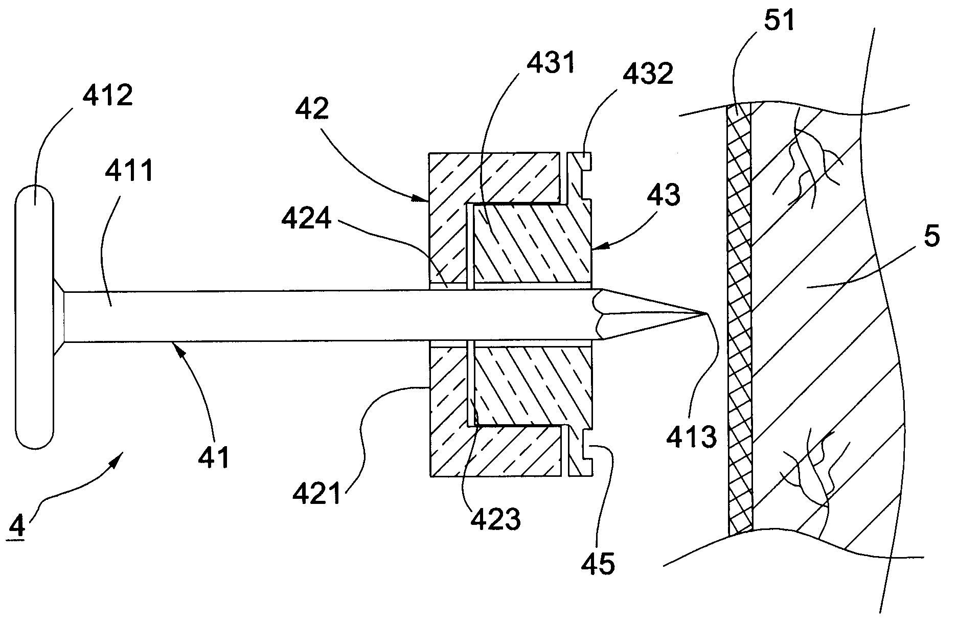
[0026]Referring to FIGS. 5 and 6 showing a first preferred embodiment of the present invention, an assemblage of sealing nail 4 is to be nailed into a plank 5 with waterproof membrane 51 for a meshed net 6 (not shown in the Figs) being hung thereon to proceed with grouting. The assemblage of sealing nail 4 essentially comprises a nail 41, a propeller 42 for the nail 41 to penetrate, and a blocker 43 partially set in the propeller 42 for the nail 41 to further penetrate. Wherein, the nail 41 has an axial shank 411, a head 412 disposed on one end of the shank 411, and a tip 413 disposed on the other end of the shank 411. Further, the propeller 42 has a top surface 421, a bottom surface 422 oppositely disposed to the top surface 421, an opened chamber 423 defined from the bottom surface 422 toward the top surface 421, and an aperture 424 defined o...


PUM


Abstract

The present invention pertains to an assemblage of sealing nail essentially containing a nail, a propeller, and a blocker that is partially extended beyond the propeller. Wherein, the nail would sequentially penetrate the propeller, the blocker, and then a plank. By means of the nail entering the plank, the propeller and the blocker would be simultaneously urged to densely cover up where the nail inserted. Therefore, a preferred sealing efficiency between the nail and the plank is achieved to guarantee a favorable grouting on the plank.

Description

BACKGROUND OF THE INVENTION[0001]1. Field of the Invention[0002]The present invention relates to an assemblage, in particular to an assemblage of sealing nail.[0003]2. Description of the Related Art[0004]Referring to FIGS. 1 and 2 showing a self-sealing fastener 1 of Anderson, disclosed by U.S. Pat. No. 6,035,595, is nailed to a plank 2 with a tarpaper 21 for a meshed net 3 to be hung thereon to proceed grouting. The conventional invention consists of a sealing member 11 and a nail 12 penetrating the sealing member 11. Wherein, the sealing member 11 includes a case 111 for the nail 12 to insert, a pusher 112 received in the case 111 for the nail 12 to insert, and an caulking unit 113 filled in the case 11 for being pushed by the pusher 112. Moreover, the meshed net 3 is placed between the sealing member 11 and the nail head. The pusher 112 protrudes toward the orientation of the nail head which arranging the pusher 112 within the case 111. The case 111 further has a plurality of rib...

Claims


Application Information

Patent Timeline
Patent Type & Authority Applications(United States)
IPC IPC(8): F16B15/00E04F13/04F16B43/00
CPCE04F13/045F16B43/001F16B15/00
Inventor YU, BO-ZHANG
Owner YU BO ZHANG
Why Eureka
Try Eureka