Wave gear device

a wave gear and gear body technology, applied in the direction of gearing, gearing elements, hoisting equipment, etc., can solve the problems of reducing elliptical deformation becoming harder to achieve, and increasing the rigidity so as to increase the bottom fatigue strength of the flexible external toothed gear, the effect of enhancing the bottom fatigue strength and increasing the load capacity

Active Publication Date: 2010-08-26
HARMONIC DRIVE SYST IND CO LTD
View PDF7 Cites 10 Cited by
  • Summary
  • Abstract
  • Description
  • Claims
  • Application Information

AI Technical Summary

Benefits of technology

[0028]According to the present invention, setting the rim thickness of the flexible externally toothed gear as described above makes it possible to increase the bottom fatigue strength of the flexible externally toothed gear in a cup-type or “silk hat”-type wave gear device subjected to bending deformation, stretching deformation, and repeated flexural deformation (coning). Furthermore, optimizing the effective width of the external teeth of the flexible externally toothed gear makes it possible to obtain results whereby the bottom fatigue strength is enhanced by optimizing the rim thickness of the gear.
[0029]As a result, according to the present invention, it is possible to attain a cup-type or “silk hat”-type wave gear device having a markedly higher load capacity than in the prior art.

Problems solved by technology

Not only does increasing the face width beyond a reasonable limit fail to produce a satisfactory tooth flank load distribution across the entire face width, but the rigidity of the flexible externally toothed gear also increases, and elliptical deformation becomes harder to achieve, inviting the opposite effect of a decrease in the bottom fatigue strength of the flexible externally toothed gear.

Method used


Image

  • Wave gear device
  • Wave gear device
  • Wave gear device

Examples


Embodiment Construction

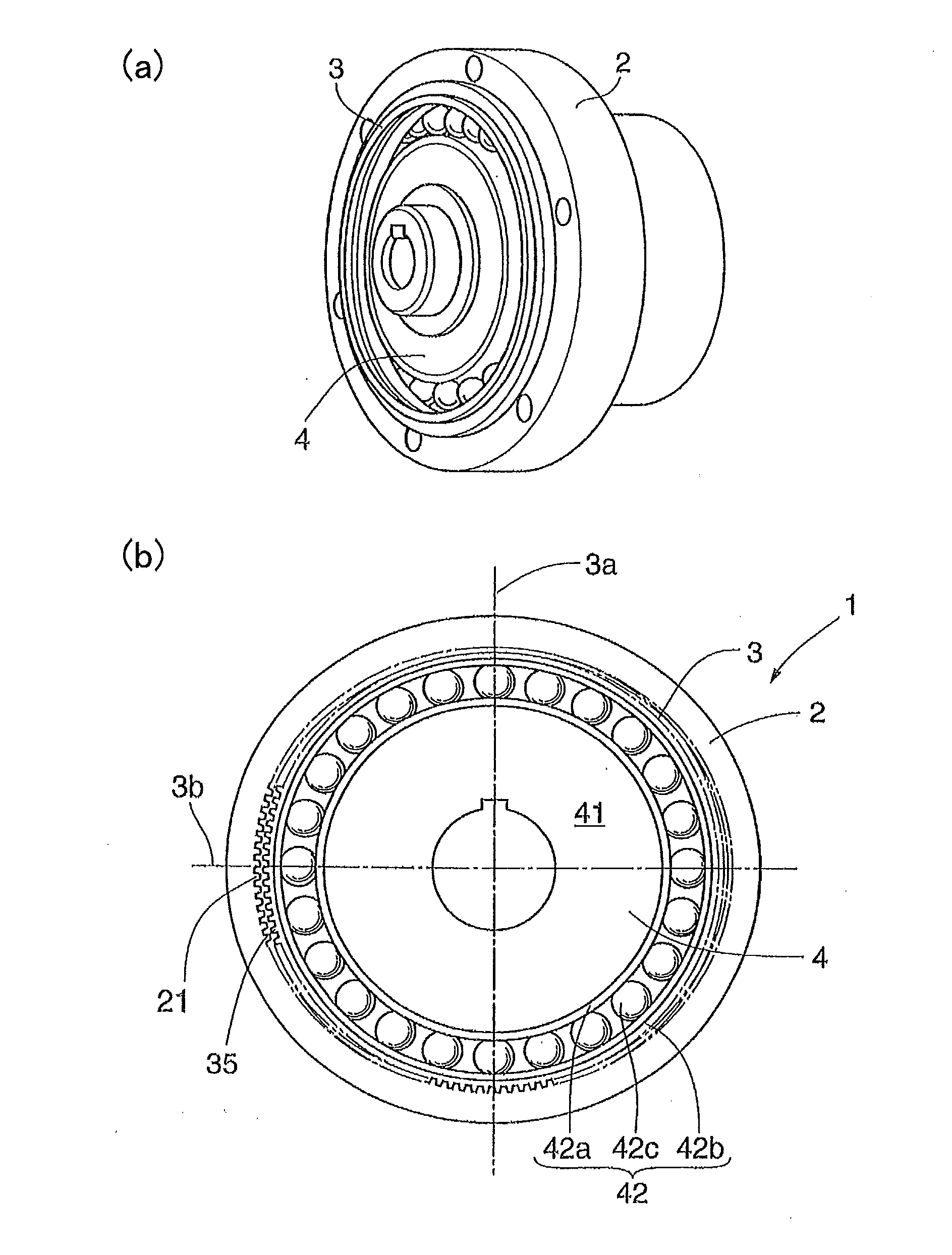
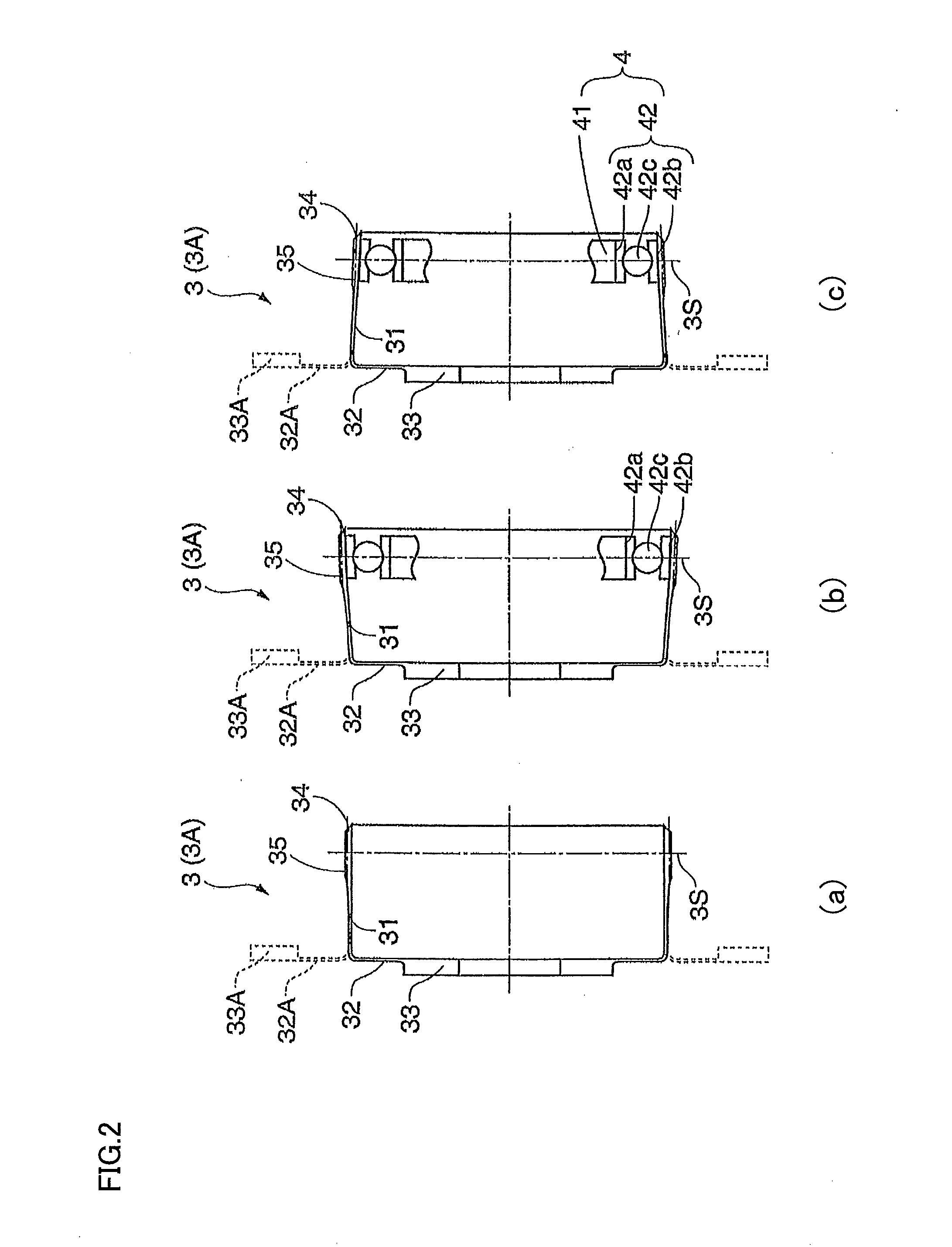
[0038]Embodiments of a cup-type or “silk hat”-type wave gear device according to the present invention are described below with reference to the accompanying drawings. The entire structure of either the cup-type or “silk hat”-type wave gear device is the same as the typical structure shown in FIGS. 1 and 2.

[0039](Rim Thickness of Flexible Externally Toothed Gear)

[0040]FIG. 3 is a conceptual diagram showing the rim thickness of a cup-shaped or “silk hat”-shaped flexible externally toothed gear in a cup-type or “silk hat”-type wave gear device. In the diagram, the rim thickness is the thickness of the portion designated by “t.” The radial deflection d of the flexible externally toothed gear 3 bent into an elliptical shape by the elliptical wave generator 4 is the radial deflection, measured at the position of the major axis of the elliptical shape in the neutral circle of the rim, in an axially perpendicular cross-section perpendicular to the axis of the gear 3, at an arbitrary positi...


PUM


Abstract

In a cup-type or “silk hat”-type wave gear device (1), the rim thickness t of the flexible externally toothed gear (3) thereof satisfies the relations (0.5237Ln(R)−1.32)d≦t≦(0.8728Ln(R)−2.2)d if the reduction ratio R of the wave gear device is less than 80, and (1.5499Ln(R)−5.8099)d≦t≦(2.5832Ln(R)−9.6832)d if the reduction ratio R is equal to or greater than 80, where d is the radial deflection, measured at the position of the major axis of the neutral circle of the rim, in a state in which the flexible externally toothed gear is bent into an elliptical shape. The effective face width L of the external teeth (35) is a value within the range of 21 to 30% of the pitch circle diameter. Such settings make it possible to increase the bottom fatigue strength of the flexible externally toothed gear and improve the load capacity of the wave gear device (1).

Description

TECHNICAL FIELD [0001]The present invention relates to a cup-type wave gear device comprising a cup-shaped flexible externally toothed gear, or to a “silk hat”-type wave gear device comprising a “silk hat”-shaped flexible externally toothed gear, and more particularly relates to an improvement technique for increasing the bottom fatigue strength of the flexible externally toothed gear and providing a strengthened wave gear device.BACKGROUND ART[0002]After the wave gear device (Patent Document 1: U.S. Pat. No. 2,906,143) was invented by the original inventor C. W. Musser, a variety of inventions have been devised by many researchers. For example, wave gear devices are disclosed in Patent Document 2 (JP-B 45-41171) and Patent Document 3 (JP-A 7-167228).[0003]A type of wave gear device having a cup-shaped or “silk hat”-shaped flexible externally toothed gear is known as the typical wave gear device. FIG. 1 is a perspective view of a cup-shaped wave gear device, and a schematic cross-se...

Claims


Application Information

Patent Timeline
Patent Type & Authority Applications(United States)
IPC IPC(8): F16H55/14F16H55/02F16H55/06
CPCF16H49/001F16H55/0833Y10T74/19967Y10T74/19F16H2049/003F16H1/28F16H1/32
Inventor ZHANG, XIN YUE
Owner HARMONIC DRIVE SYST IND CO LTD
Why Eureka
Try Eureka